Magnetoresistance effect device, method of manufacturing the same, magnetic memory apparatus, personal digital assistance, and magnetic reproducing head, and magnetic information reproducing apparatus

a technology of magnetic resistance and effect, which is applied in the field of magnetic resistance effect devices, can solve the problems of loss of fineness and controllability of drawn pattern shapes, lack of sharpness at each corner, etc., and achieve the effect of simple and highly productive manufacturing methods

Inactive Publication Date: 2002-09-19
KK TOSHIBA
View PDF0 Cites 29 Cited by
  • Summary
  • Abstract
  • Description
  • Claims
  • Application Information

AI Technical Summary

Benefits of technology

0028] Yet another object of present invention to provide a simple highly productive manufacturing method for a magnetoresistance effect device.
0029] These and other objects are achieved by providing a novel magnetoresistance effect device including a first ferromagnetic layer, a first nonmagnetic dielectric layer formed on the first ferromagnetic layer, and a second ferromagnetic layer formed on the first nonmagnetic dielectric layer. Further, one of the first and second ferromagnetic material layers includes a plane shape in which a center region is disposed between first and second end regions, and the center region has a width narrower than each width of the first and second end regions. A novel manufacturing method is also provided.

Problems solved by technology

In regard to the manufacturing method of the TMR device using an EB drawing, back scattering of EB at a surface of metal layer, such as ferromagnetic layers and nonmagnetic material layer, is stronger than a semiconductor material layer, a known proximity effect of considerably widening a provided drawing pattern becomes significant, whereby fineness and controllability of a drawn pattern shape is lost.
As a result, even when a rectangle is intended to be drawn as a shape of a ferromagnetic tunnel junction, the resultant shape lacks sharpness at each of the corners.

Method used


Image

  • Magnetoresistance effect device, method of manufacturing the same, magnetic memory apparatus, personal digital assistance, and magnetic reproducing head, and magnetic information reproducing apparatus
  • Magnetoresistance effect device, method of manufacturing the same, magnetic memory apparatus, personal digital assistance, and magnetic reproducing head, and magnetic information reproducing apparatus
  • Magnetoresistance effect device, method of manufacturing the same, magnetic memory apparatus, personal digital assistance, and magnetic reproducing head, and magnetic information reproducing apparatus

Examples


first embodiment

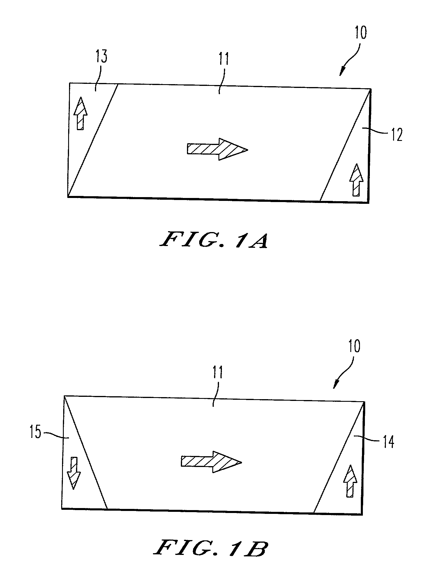
[0077] Turning now to FIG. 2, which is a plan view of a ferromagnetic layer 20 according to the present invention. As shown, the ferromagnetic layer 20 has a plane shape and includes a center portion formed between two end portions so as to align with each other. Each of the end portions has a width wider than the center portion, and has an extended additional portion. Further, each of the extended portions of the ferromagnetic layer can be thought of as being added to a rectangular-shaped ferromagnetic layer. Further, each of the extended portions are substantially symmetrical aligned to each other with a substantial center point (x) of the ferromagnetic material layer 20 as a pivot. Although each of the extended additional portions in FIG. 2 are substantially symmetrical aligned with the substantial center point (x) as the pivot, a precise adjustment of their symmetry and proportional breadth is not required and both extended portions may be unsymmetrical and have different breadt...

second embodiment

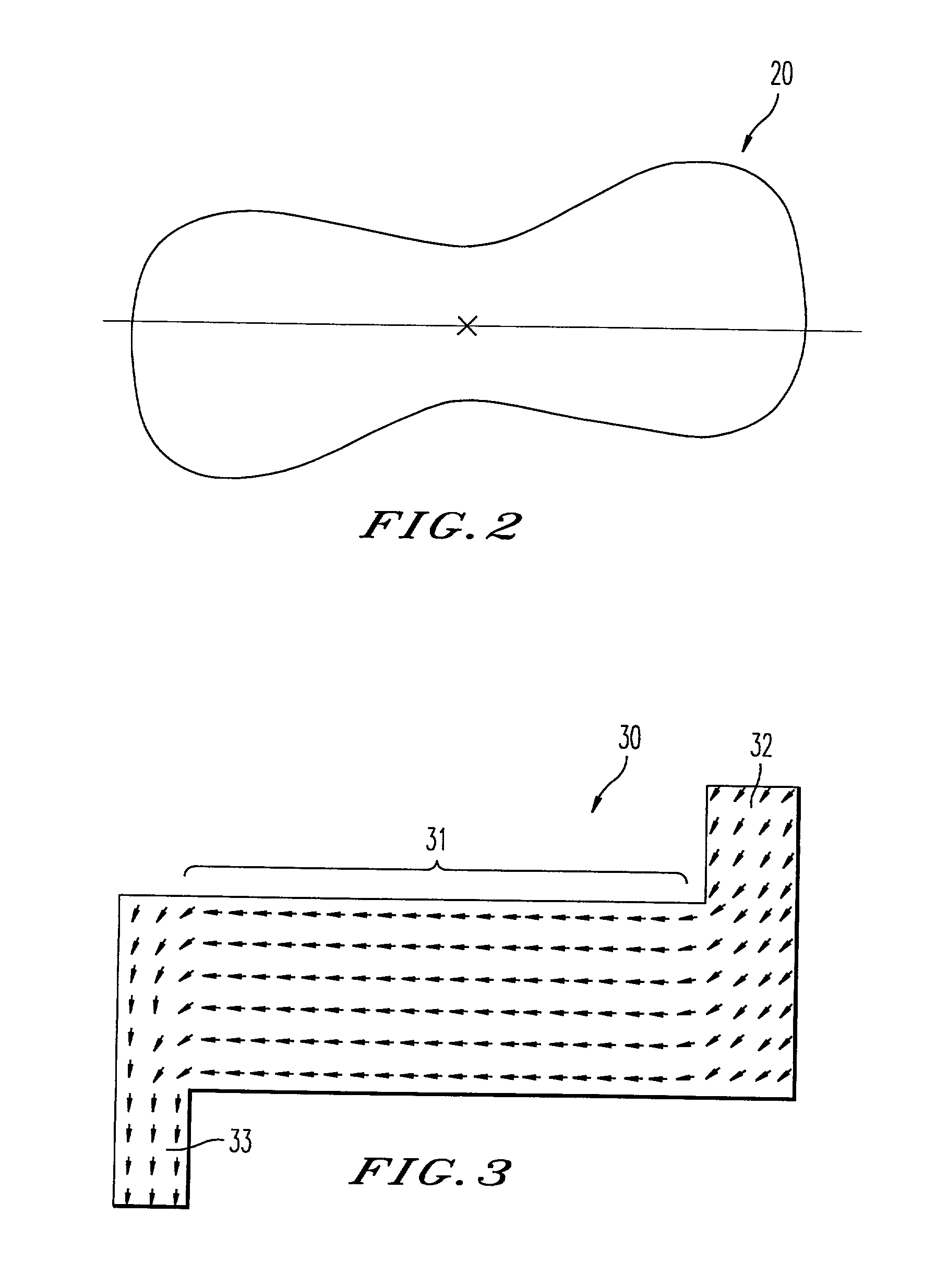
[0079] Turning now to FIG. 3, which is a plan view of a ferromagnetic layer including arrows for indicating a magnetization of the ferromagnetic layer according to the present invention.

[0080] As shown, the ferromagnetic layer 30 has hooked-portions 32 and 33 at end portions to form an S-like shape. Further, the widths of the hooked-portions are different from a width of the center portion 31. The center portion 31 has a continuous width of 0.1 .mu.m and each end portion 32 and 33 has a width of 0.15 .mu.m. The layer 30 also has a length of 0.4 .mu.m and an average thickness of 1.5 .mu.m.

[0081] The widths of the two end portions can be different from each other. The magnetization free layer or film receives a stray magnetic field of the magnetization pinned layer, whereby its magnetization hysteresis under a one-directional magnetic field that is in parallel to the longer axis of the magnetization free layer may be different from its magnetization hysteresis under another magnetic f...

third embodiment

[0094] Now, FIG. 7B is a plan view of a ferromagnetic layer of a magnetoresistance effect device according to the present invention.

[0095] As shown, the ferromagnetic layer 75 has semicircle-shaped extended portions 76 and 77. Further, the semicircle-shaped extended portions 76 and 77 have a gradually changing magnetization as indicated by the arrows in FIG. 7B. The layer's magnetic domains were calculated for a ferromagnetic material of Co.sub.9Fe. Other magnetic materials such as Fe, Co, Ni, or their alloys and a laminated film of the ferromagnetic material layers can also be used. The laminated film may also have a nonmagnetic metal layer including Cu, Au, Ru, Al or the equivalents.

[0096] FIG. 8 is a diagram of a calculated magnetization curve of the ferromagnetic layer in FIG. 7B according to the third embodiment of the present invention. As shown, the coercive force Hc was as low as 148 (Oe) and a rate of residual magnetization to saturation magnetization was as high as 0.96. A...


PUM

PropertyMeasurementUnit
widthaaaaaaaaaa
widthaaaaaaaaaa
thicknessaaaaaaaaaa

Abstract

Magnetoresistance effect devices for attaining magnetically stability and for reducing a switching magnetic field. One of the ferromagnetic layers of the magnetoresistance effect device has a plane shape in which a width of an end portions is wider than a center portion sandwiched by two end portions. The end portions are not symmetrical with respect to an easy magnetization axis or longer axis of the plane shape of ferromagnetic material layer, but are substantially rotationally symmetrical with a center of the plane shape as a pivot. The plane shape may have an S-shape where its magnetic domain is stabilized and the switching magnetic field is reduced. The manufacturing method uses two linear mask patterns intersecting with each other to form sharp corners of a ferromagnetic tunnel junction. An electron beam (EB) drawing may be used to form the S-shape plane. The magnetoresistance effect devices may be used in a magnetic memory apparatus, such as a random access memory, a personal digital assistance, a magnetic reproducing head, and a magnetic information reproducing apparatus.

Description

CROSS REFERENCE TO A RELATED APPLICATION[0001] This application claims the benefit of priority from Japanese Patent Application No. 2001-076614, filed on Mar. 16, 2001, the entire contents of which are incorporated herein by reference.BACKGROUND OF THE INVENTION[0002] 1. Field of the invention[0003] The present invention relates to a magnetoresistance effect device, a method of manufacturing the same, a magnetic memory apparatus, a personal digital assistance, a magnetic reproducing head and a magnetic information reproducing apparatus.[0004] 2. Discussion of the Background[0005] Solid magnetic memories including a Magnetic Random Access Memory (MRAM) using a MagnetoResistance (MR) effect element have been proposed. Further, a Tunnel MagnetoResistance effect device (TMR device) that uses a ferromagnetic tunnel junction has recently drawn attention as a component of a memory cell of the MRAM.[0006] A conventional ferromagnetic tunnel junction has a three-layered film including a firs...

Claims


Application Information

Patent Timeline
Patent Type & Authority Applications(United States)
IPC IPC(8): G01R33/09G11B5/39G11C11/14G11C11/15G11C11/16H01F10/16H01F10/32H01L21/8246H01L27/105H01L27/22H01L43/08H01L43/12
CPCB82Y10/00Y10T428/24942G11B5/3903G11B5/3909G11B5/398G11B2005/3996H01F10/3254H01L27/228H01L43/08Y10S428/90Y10T428/265Y10T29/49052Y10T428/26Y10T428/32Y10T29/4905Y10T29/49043Y10T29/49048G11C11/161B82Y25/00H10B61/22H10N50/10
Inventor KISHI, TATSUYATAKAHASHI, SHIGEKINAKAJIMA, KENTAROAMANO, MINORUSAGOI, MASAYUKISAITO, YOSHIAKI
Owner KK TOSHIBA
Why Eureka
Try Eureka