Device with a diaphragm arrangement

a diaphragm and device technology, applied in the direction of fluid pressure control, process and machine control, instruments, etc., can solve the problems of increasing the effort and expense of producing the diaphragm arrangement, the inability to multi-layer construction the diaphragm arrangement, and the requirement for producing the lower retaining elemen

Inactive Publication Date: 2002-09-26
ROBERT BOSCH GMBH
View PDF0 Cites 4 Cited by
  • Summary
  • Abstract
  • Description
  • Claims
  • Application Information

AI Technical Summary

Problems solved by technology

In this arrangement it is disadvantageous that the encompassing bead formed onto the diaphragm arrangement increases the effort and expense of producing the diaphragm arrangement considerably, and in this diaphragm arrangement, a multi-layer construction of the diaphragm arrangement is practically impossible.
Another disadvantage is that because of the encompassing groove, producing the lower retaining element requires considerably more effort and expense.
Because of the encompassing groove, it is very complicated to produce the retaining element that has the groove; in particular, the retaining element must be reshaped quite severely and made to assume a complicated shape.
Because of the complicated shape of the retaining element, otherwise conventional materials cannot be used, and rapid wear of the stamping tool used in producing the retaining element must be feared.
However, in this arrangement it must be feared that the diaphragm arrangement will become damaged at its fastening point during the crimping over the retaining element.
Because of the bending over of the diaphragm arrangement, diaphragms comprising multiple layers cannot be used.
Because the additional sealing ring is only very inadequately compartmentalized, subsidence and resultant leaks must be feared.
Another factor is that the sealing ring cannot provide sealing directly in the region of the diaphragm fastened in place.
Because of the requisite sealing ring groove, a diaphragm arrangement that is simple to produce cannot be used.

Method used


Image

  • Device with a diaphragm arrangement
  • Device with a diaphragm arrangement
  • Device with a diaphragm arrangement

Examples


Embodiment Construction

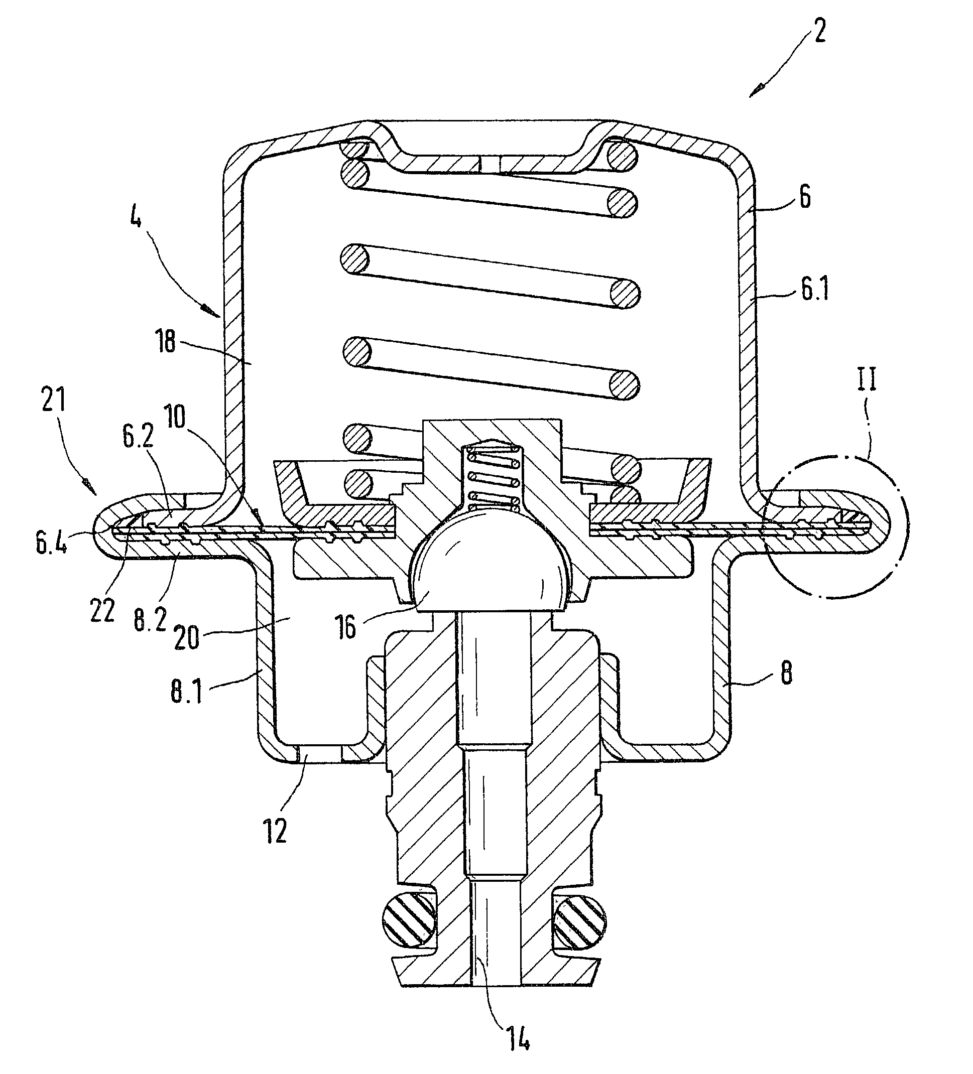
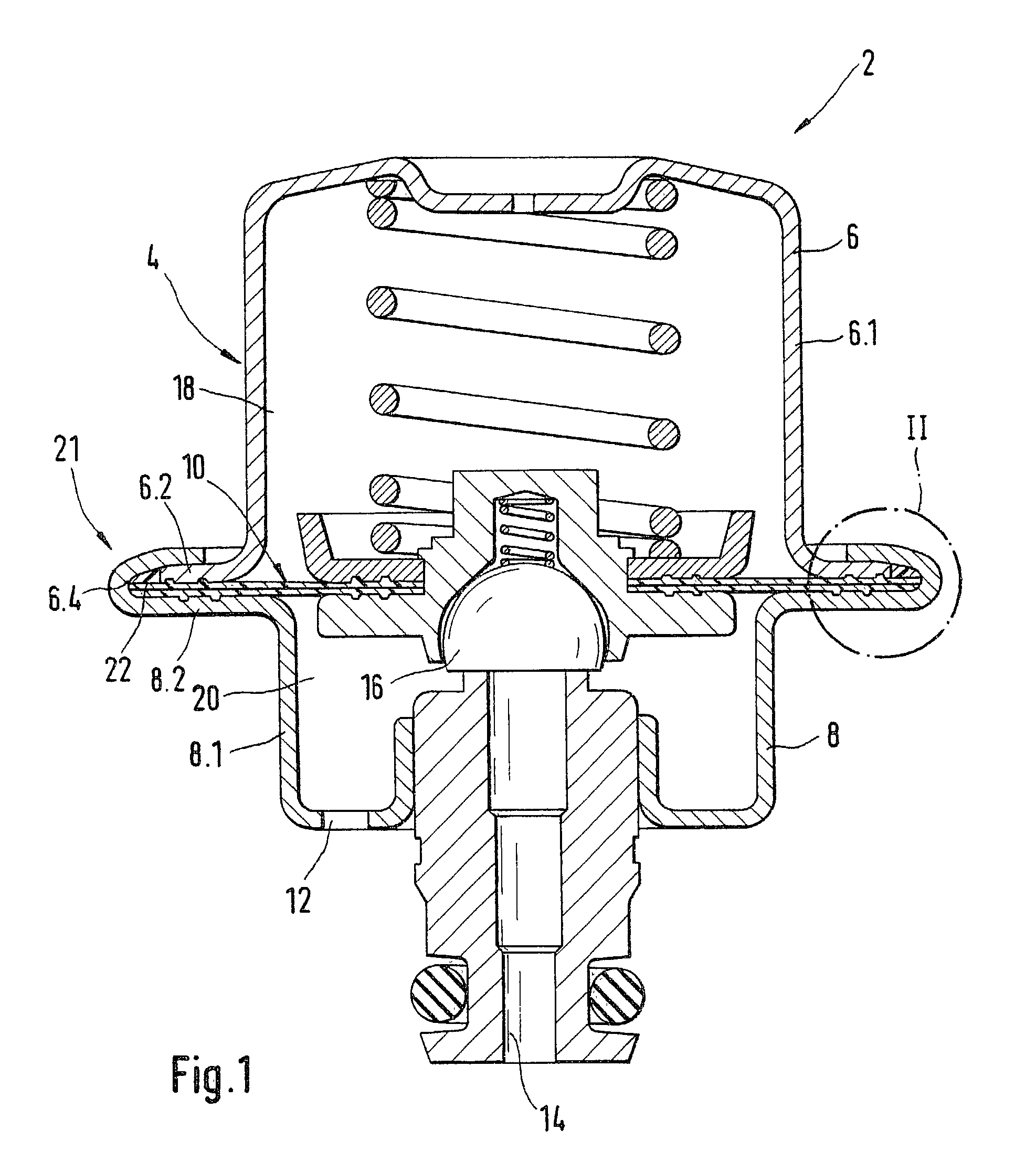
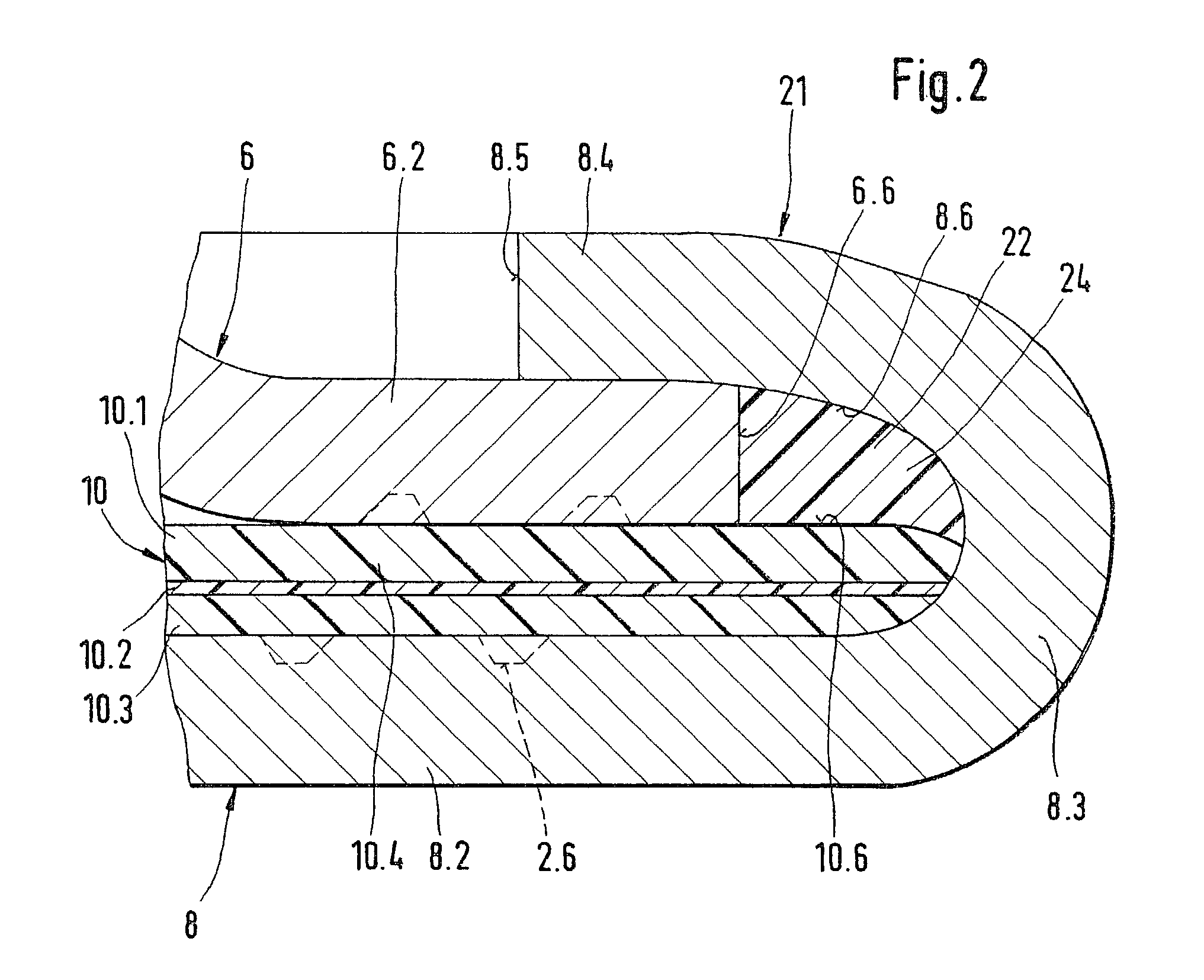
[0014] The device with a diaphragm arrangement, explained according to the invention, can be used whenever a diaphragm arrangement is fastened in place between two retaining elements crimped to one another.

[0015] The device is for instance a hydraulic pressure reservoir, in which a liquid is located on one side of the diaphragm arrangement, for instance, and a gas under pressure is located on the other side of the diaphragm arrangement.

[0016] The device can, however, also be a pressure valve, for example, in which the liquid whose hydraulic pressure is to be controlled is located on one side of the diaphragm arrangement, and atmospheric pressure, for instance, or a reference pressure is located on the other side of the diaphragm arrangement. The pressure valve is used for instance for controlling or regulating a pressure of fuel in a fuel supply system of an internal combustion engine. An Otto engine can for instance be considered as the internal combustion engine. The fuel is for i...


PUM


Abstract

In devices with a diaphragm arrangement crimped into place and dividing two chambers from one another, until now functional problems arose at elevated pressures, because in permanent operation the diaphragm arrangement shifted, or because of leaks. In the device (2) proposed here, with a diaphragm arrangement (10) retained via a crimped connection (21), excellent restraint of the diaphragm arrangement (10) and excellent sealing are attained with the aid of an elastomer material (22). The device is a pressure valve, for instance, and serves to vary a pressure of a fuel supply system of a motor vehicle.

Description

PRIOR ART[0001] The invention is based on a device with a diaphragm arrangement as generically defined by the preamble to claim 1.[0002] European Patent EP 0 585 810 B1 shows a device for the diaphragm arrangement, having a first retaining element and a second retaining element. The diaphragm arrangement is fastened between the two retaining elements. An encompassing bead is formed onto the outer circumference of the diaphragm arrangement. The bead is located in an encompassing groove provided in the lower retaining element. In this arrangement it is disadvantageous that the encompassing bead formed onto the diaphragm arrangement increases the effort and expense of producing the diaphragm arrangement considerably, and in this diaphragm arrangement, a multi-layer construction of the diaphragm arrangement is practically impossible. Another disadvantage is that because of the encompassing groove, producing the lower retaining element requires considerably more effort and expense.[0003]...

Claims


Application Information

Patent Timeline
Patent Type & Authority Applications(United States)
IPC IPC(8): F16K17/04F02M69/00F16K41/12G05D16/06
CPCF16K41/12G05D16/0633G05D16/0658Y10T137/7836F02M69/54
Inventor TOMCZAK, STANISLAUSHOEPFL, ROLANDITTLINGER, RALPHHUDEC, VOLKER
Owner ROBERT BOSCH GMBH
Why Eureka
Try Eureka