
Cathode ray tube having a frame/mask assembly

a cathode ray tube and frame technology, applied in the field of colour cathode ray tubes, can solve the problems of high material cost and high weight, the mask cannot be welded directly to the frame, and the image is reproduced on the screen decolorized

Inactive Publication Date: 2002-09-26
THOMSON LICENSING SA
View PDF0 Cites 3 Cited by
  • Summary
  • Abstract
  • Description
  • Claims
  • Application Information

AI Technical Summary

Benefits of technology

0013] To do this, the frame/mask assembly according to the present invention comprises a colour selection mask and a substantially rectangular metal frame for supporting the mask and holding it in tension in at least one direction, the mask being made from a material whose coefficient of thermal expansion is less than the coefficient of thermal expansion of the materi...

Problems solved by technology

The mask no longer being flat, it follows that the points of impingement of the three electron beams on the screen of the tube no longer correspond to the ad hoc lines of luminescent materials, thus causing a decoloration of the image reproduced on the said screen.
This solution then exhibits the drawbacks of high material costs and high weight.
The tension mask cannot be welded directly to the frame which holds it in tension unless the said frame is made from a material whose coefficient of thermal expansion is similar to that of the mask, and it cannot in particular be made from standard steel.
; at these temperatures the differential in the expansion of the materials where the mask is welded to the frame may cause local failures of the weld and hence local and random modifications to the tension of the mask, modifications giving rise to defects in the colours of the image reproduced on the screen of the tube.
This solution therefore necessitates the use of a frame and a mask whose coefficients of thermal expansion are similar and small, for example made of Invar; however, this type of material is much more expensive than standard steel, around three times more expensive, thereby very considerably increasing the cost of the frame and consequently of the manufactured tube.

Method used


Image

  • Cathode ray tube having a frame/mask assembly
  • Cathode ray tube having a frame/mask assembly
  • Cathode ray tube having a frame/mask assembly

Examples


Embodiment Construction

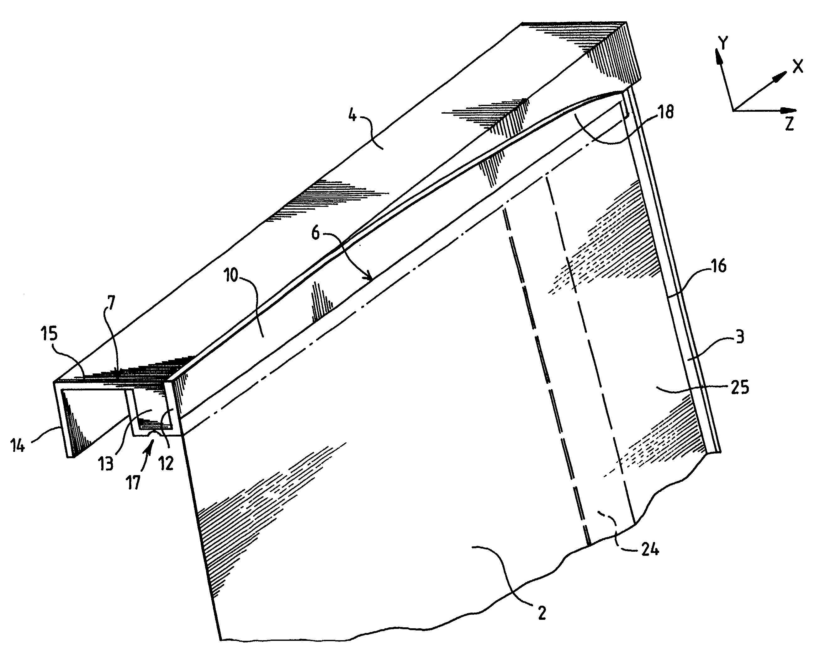
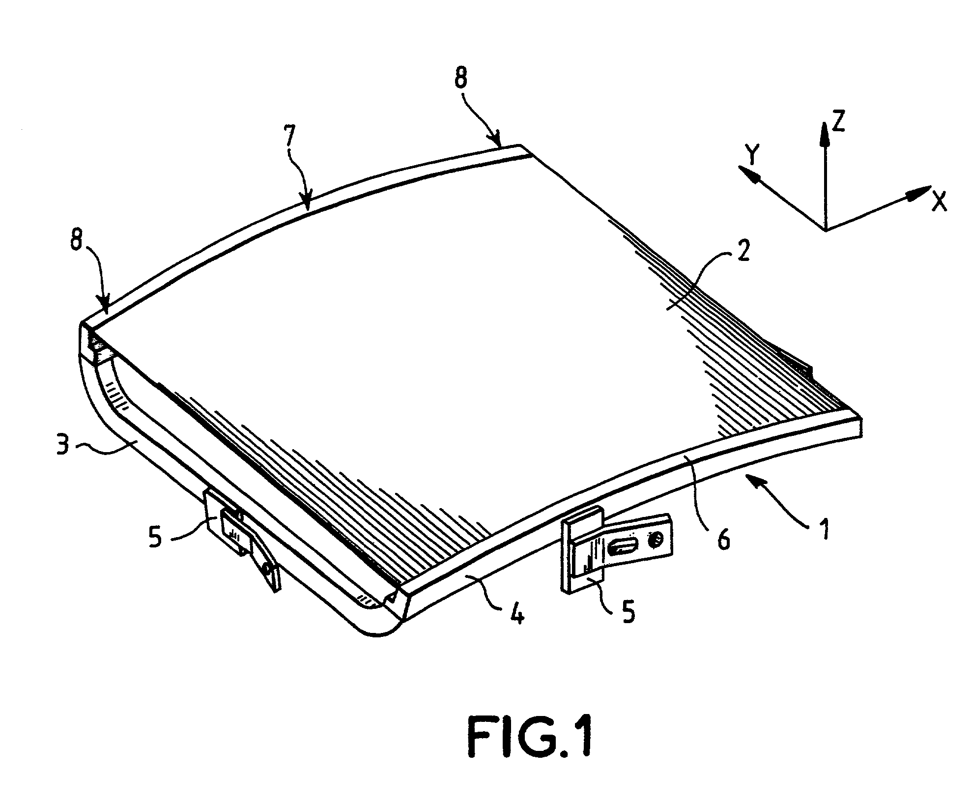
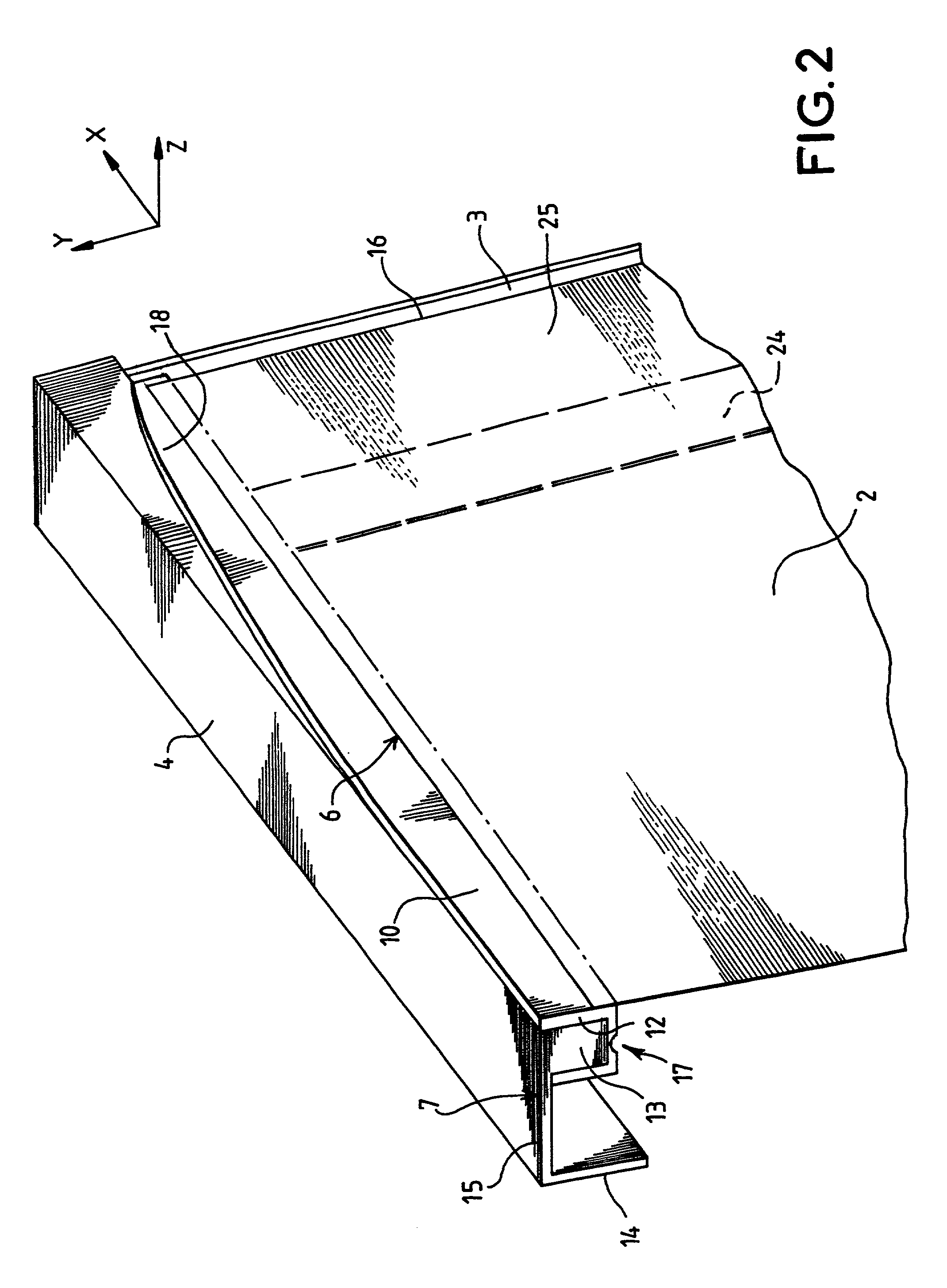
[0019] FIG. 1 illustrates a frame / mask assembly according to the state of the art such as described in Patent No. GB2308223. The directions along X, Y, Z, respectively, represent the directions along the horizontal and vertical axes and the main axis of the tube perpendicular to the surface of the display screen. The substantially rectangular frame 1 is composed of two horizontal long sides 4 and of two vertical short sides 3. The frame 1 holds a colour selection mask 2 in tension along at least one direction, parallel to the short sides of the frame. Suspensions 5 are intended to cooperate with metal studs inserted into the skirt of the faceplate of the cathode ray tube so as to keep the frame / mask assembly a precise distance from the screen of the tube.

[0020] The quality of the welding of the mask 2 along the edges of the sides 4 of the frame is what guarantees that the tension of the said mask will be maintained according to preset values with, for example, a higher tension in th...


PUM


Abstract

A cathode ray tube comprising a color selection mask made from a material in tension and having a relatively low coefficient of thermal expansion, supported by a frame made from a material having a higher coefficient of thermal expansion. Along at least two sides of the frame are disposed two metal inserts made from a material whose coefficient of thermal expansion is similar to that of the mask. The inserts are secured to the opposed sides of the frame at their middle, and the mask is welded to the inserts. The mechanical problems relating to the differences in expansion of the materials making up the mask and the frame, during the high-temperature tube manufacturing steps, are avoided.

Description

FIELD OF THE INVENTION[0001] The invention relates to a colour cathode ray tube and more particularly to the frame / colour selection mask system disposed inside the glass envelope of the tube. The invention finds its application in any type of tube comprising a colour selection mask and is more particularly adapted to tubes whose mask is held in tension by the frame to which it is secured.BACKGROUND OF THE INVENTION[0002] Conventional cathode ray tubes comprise a colour selection mask situated a precise distance from the inside of the glass faceplate of the tube, on which faceplate are deposited arrays of red, green and blue luminophores. Under the influence of three electron beams each corresponding to a specified primary colour, the arrays of luminophores allow the reproduction of images on the screen, the mask allowing each specified beam to illuminate only the luminophore of the corresponding colour.[0003] The colour selection mask must be disposed and held during the operation o...

Claims


Application Information

Patent Timeline
IPC IPC(8): H01J29/07
CPCH01J29/073H01J2229/0722
Inventor DE MARINO, MASSIMOTESTA, PIERLUIGI
Owner THOMSON LICENSING SA
Learn More