Data adaptive ramp in a digital filter

a data adaptive ramp and digital filter technology, applied in the field of digital filters, can solve the problems of high cost, easy parts and circuit tolerance limitations, and complex digital circuits, and achieve the effects of reducing the number of parts and circuits, reducing the complexity of digital circuits, and reducing the complexity of analog filter topologies

Inactive Publication Date: 2002-09-26
SOAR S K LIABILITY
View PDF3 Cites 33 Cited by
  • Summary
  • Abstract
  • Description
  • Claims
  • Application Information

AI Technical Summary

Problems solved by technology

At the circuit component level, digital circuits are much more complex, employing millions of devices in some circumstances.
However, at the device level, digital communications circuits are much simpler, often times using just a handful of devices to accomplish a complex communications task.
As system designs have become more stringent, with narrowing bandwidths and higher information rates, analog filter topologies had become very complex, expensive, and prone to parts and circuit tolerance limitations.
Analog filters become rather poor choices when narrow bands, close channelization, and high information rates force the need for very high order filters to meet system design criteria.
However, digital filters are not without their own limitations, and the state of the art has evolved to the point where even digital filter designs are challenged to meet tight system requirement.
However, truncating the time domain necessarily results in a broadening, or splattering, of energy bandwidth in the frequency domain.
Where a filter is used to control bandwidth, as in channelizing a communications signal, this splattering of energy can result in undesirable interference, noise, reduced system performance, and violation of FCC regulations.
The problem is of particular concern in any system where the communications of information must be started and stop with any regularity.
Thus, there is a period of time at the beginning and end of each transmission block of information which does not contribute to the communications of useful information through the system.
In effect, the data throughput performance of the system is compromised by the filter's limitations.

Method used


Image

  • Data adaptive ramp in a digital filter
  • Data adaptive ramp in a digital filter
  • Data adaptive ramp in a digital filter

Examples


Embodiment Construction

[0028] Illustrative embodiments and exemplary applications will now be described with reference to the accompanying drawings to disclose the advantageous teachings of the present invention. While the present invention is described herein with reference to illustrative embodiments for particular applications, it should be understood that the invention is not limited thereto. Those having ordinary skill in the art and access to the teachings provided herein will recognize additional modifications, applications, and embodiments within the scope thereof and additional fields in which the present invention would be of significant utility.

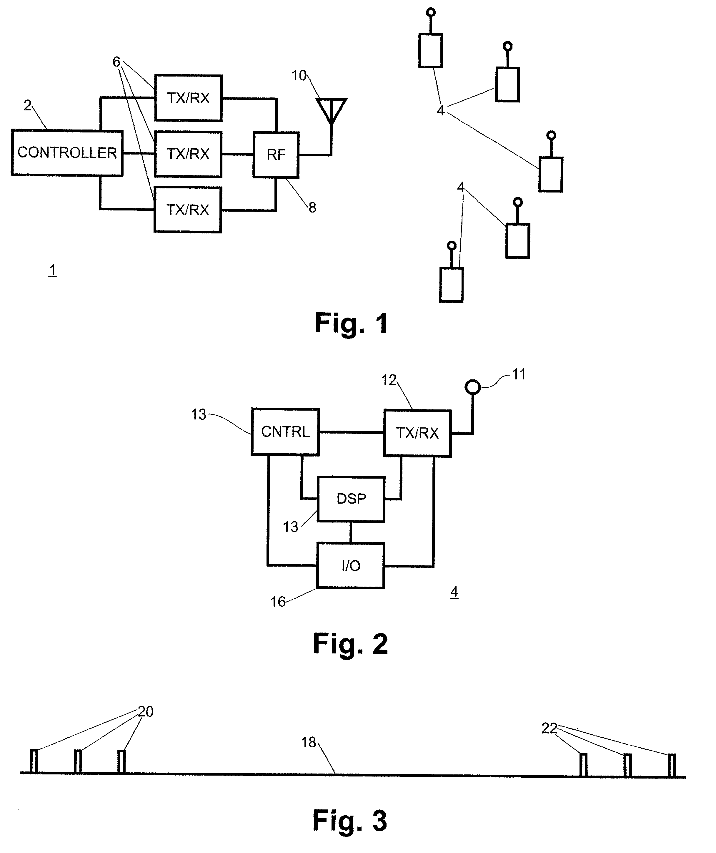
[0029] The preferred embodiment utilizes the present invention in a trunked land mobile radio system that employs FDM channelization and TDMA packetized data for channel trunking management, system control, data communications, and voice communications. Reference is directed to FIG. 1, which is a block diagram of such a system. The system includes a repe...


PUM


Abstract

A system and method for improving the performance of digital filters is disclosed. The data bandwidth and spectral control are improved by adaptively selecting ramp-up and ramp-down symbols based on the actual filtered data. Thus, the energy in the truncated tail of the filter is minimized for a given filter design. The invention is of particular utility in systems that filters intermittent data streams, thus requiring the filter to energize and deenergize repeatedly.

Description

[0001] 1. Field of the Invention[0002] The present invention relates to digital systems. More specifically, the present invention relates to digital filters used to control bandwidth in a communication system.[0003] 2. Description of the Related Art[0004] Modern communication systems have evolved from using predominantly analog circuitry to predominantly digital circuitry over the past several years. Where there use to be passive and active analog circuits used to oscillate, mix, filter and amplify signals in `analog` domain, there are now digital signal processing circuits that employ specialized microprocessors, DSP's and related circuits to process signals in the digital domain. At the circuit component level, digital circuits are much more complex, employing millions of devices in some circumstances. However, at the device level, digital communications circuits are much simpler, often times using just a handful of devices to accomplish a complex communications task. Portable wir...

Claims


Application Information

Patent Timeline
Patent Type & Authority Applications(United States)
IPC IPC(8): H03H17/02
CPCH03H17/0219
Inventor MCCARTY, ROBERT J. JR.
Owner SOAR S K LIABILITY
Why Eureka
Try Eureka