Variable valve timing apparatus

a timing apparatus and variable valve technology, applied in mechanical equipment, valve arrangements, machines/engines, etc., can solve the problems of difficult engine start, inability to secure the hydraulic pressure required to lock the rotor,

Inactive Publication Date: 2002-10-03
DENSO CORP
View PDF4 Cites 128 Cited by
  • Summary
  • Abstract
  • Description
  • Claims
  • Application Information

AI Technical Summary

Problems solved by technology

However, when the number of revolution is low, in particular, when the temperature of the hydraulic oil is high, there is the case where the hydraulic pressure is decreased to make it impossible to secure the hydraulic pressure requ

Method used


Image

  • Variable valve timing apparatus
  • Variable valve timing apparatus
  • Variable valve timing apparatus

Examples


first embodiment

ADVANTAGES OF THE FIRST EMBODIMENT

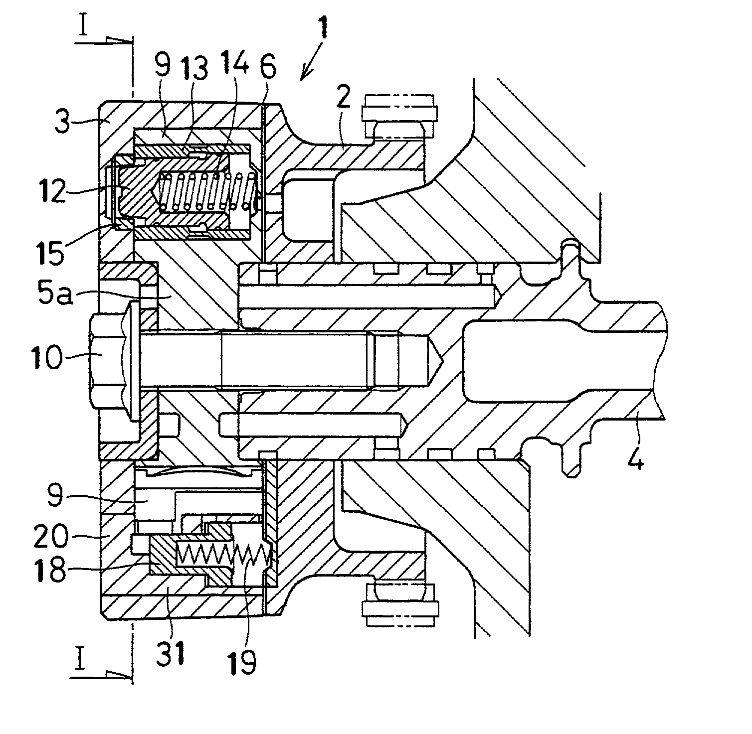
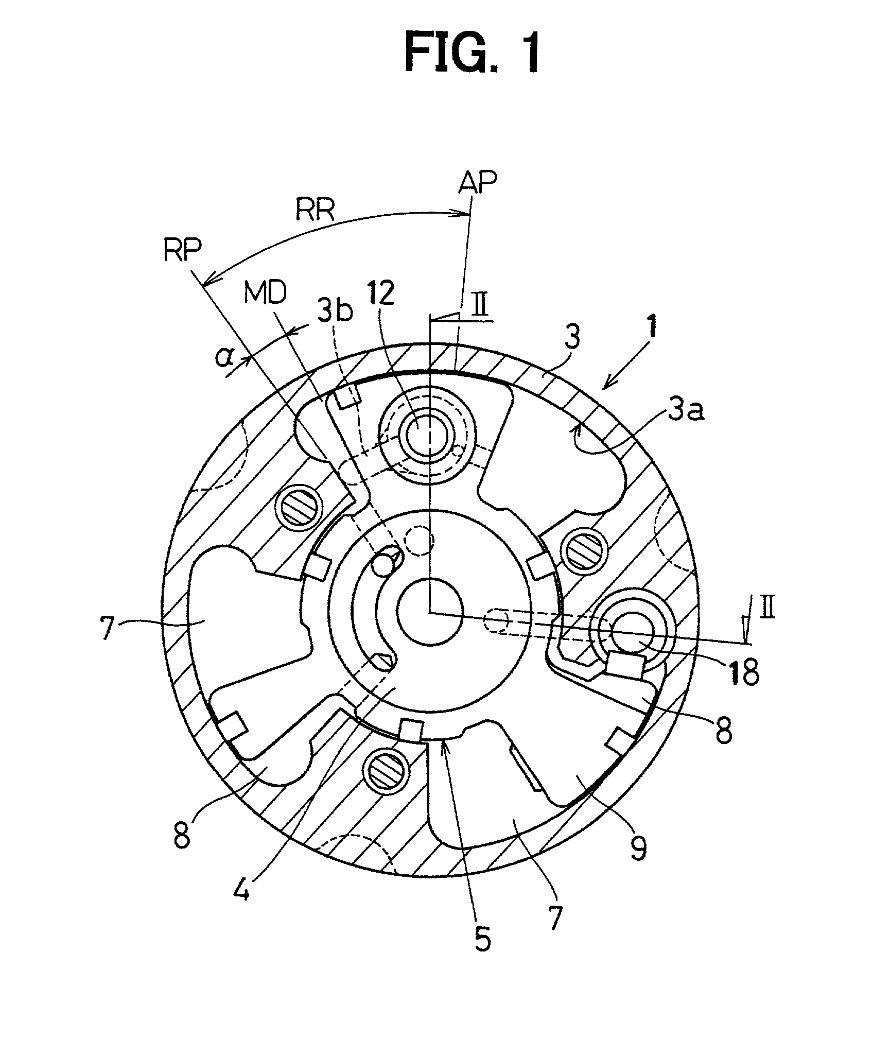
[0112] In present embodiment, there is provided with the rotor rotation restricting unit capable of preventing the rotor 5 from rotating from the normal delay angle position to the delay angle side. That is, when the engine starts, the rotor 5 can be locked at the normal delay angle position by the rotor rotation restricting unit, so that it is possible to realize a valve timing suitable for starting the engine when the engine starts. Further, by pushing down the delay angle restricting pin 18 to the retracted position to release the rotor rotation restricting unit, the rotor 5 can be rotated to the largest delay angle position, so that it is possible to realize a valve timing suitable for improving fuel consumption and increasing power after the idling operation of the engine.

[0113] Further, by keeping a balance of pressure applied to the delay angle restricting pin 18 in the first control chamber 16 and in the second control chamber 17 in the stat...

second embodiment

[0119] Since the control chambers (the first control chamber 16 and the second control chamber 17) are formed in the sleeve 20 incorporated in the case 3 in the above embodiment, the orifice 21a provided in the oil passage 21 communicating with the first control chamber 16 from the delay angle chamber 7 may be provided in the sleeve 20. In this case, for example, as shown in FIG. 9, it is possible to form the first hydraulic pressure introducing port 16a opening to the first control chamber 16 as the orifice 21a.

third embodiment

[0120] FIG. 10 is a cross sectional view of a VVT 1 (cross sectional view taken on a line X-X in FIG. 11) and FIG. 11 is a cross sectional view taken on a line XI-XI in FIG. 10.

[0121] The VVT 1 of the present embodiment is one example having a configuration in which the delay angle restricting pin 18 of the rotor rotation restricting unit can move in the radial direction.

[0122] In the rotor rotation restricting unit, as shown in FIG. 10 and FIG. 11, the delay angle restricting pin 18 can move in the radial direction with respect to the rotor 5 and can retractably move between the restricting position that blocks the rotational path of the rotor 5 and the retracted position that allows the rotor 5 to rotate.

[0123] The rotor 5 has an arc-shaped clearance groove (see FIG. 10) made within a predetermined angle range on its outer peripheral surface. This clearance groove 32 is made so as to allow the rotor 5 to rotate in the state where the delay angle restricting pin 18 is pushed out to...


PUM


Abstract

A variable valve timing apparatus rotatably receives a rotor in a housing. The rotor can rotate within a predetermined angular range. In some cases, the rotor is locked by a lock pin at an intermediate position within the angular range. In this manner, it is possible to realize a suitable valve timing even when an engine is restarted after it is stopped. In some case, the rotor is prevented from moving to the largest delay angle position by a restricting pin. In this manner, it is possible to prevent the rotor from reaching the largest delay angle position before the engine is stopped. On the other hand, while the engine is operated, it is possible to rotate the rotor to the largest delay angle position and to realize a valve timing responsive to the state of operation.

Description

[0001] This application is based on Japanese Patent Applications No. 2001-92350 filed on Mar. 28, 2001, No. 2001-98078 filed on Mar. 30, 2001, No. 2001-285280 filed on Sep. 19, 2001, and No. 2002-13119 filed on Jan. 22, 2002 the contents of which are incorporated herein by reference.[0002] 1. Field of the Invention[0003] The present invention relates to a variable valve timing apparatus for varying an opening / closing timing of an intake valve or an exhaust valve of an internal combustion engine.[0004] 2. Description of Related Art[0005] A variable timing mechanism is disclosed in JP-A No. 9-324613. This variable timing mechanism employs a lock pin capable of locking a rotor at a position (hereinafter referred to as intermediate phase position) where the rotor rotates a predetermined angle to an advance angle side from the largest delay angle position. When an engine starts, this lock pin is engaged with a lock depressed portion to lock the rotor at the intermediate phase position to...

Claims


Application Information

Patent Timeline
IPC IPC(8): F01L1/34F01L1/344
CPCF01L1/34F01L1/344F01L2001/3443F01L2001/34483F01L2001/34469F01L2001/34473F01L2001/34476F01L2001/34466F01L1/3442
Inventor TAKENAKA, AKIHIKO
Owner DENSO CORP
Why Eureka
Try Eureka