Adjustable shadow mask for improving uniformity of film deposition using multiple monitoring points along radius of substrate

a film deposition and uniformity technology, applied in the field of thin film deposition systems, can solve the problems of undesirable deposition in the center and limited control

Inactive Publication Date: 2002-10-03
SUPER TALENT ELECTRONICS
View PDF0 Cites 57 Cited by
  • Summary
  • Abstract
  • Description
  • Claims
  • Application Information

AI Technical Summary

Problems solved by technology

While using a shadow mask can improve film uniformity, the degree of control is limited since one of only thr

Method used


Image

  • Adjustable shadow mask for improving uniformity of film deposition using multiple monitoring points along radius of substrate
  • Adjustable shadow mask for improving uniformity of film deposition using multiple monitoring points along radius of substrate
  • Adjustable shadow mask for improving uniformity of film deposition using multiple monitoring points along radius of substrate

Examples


Embodiment Construction

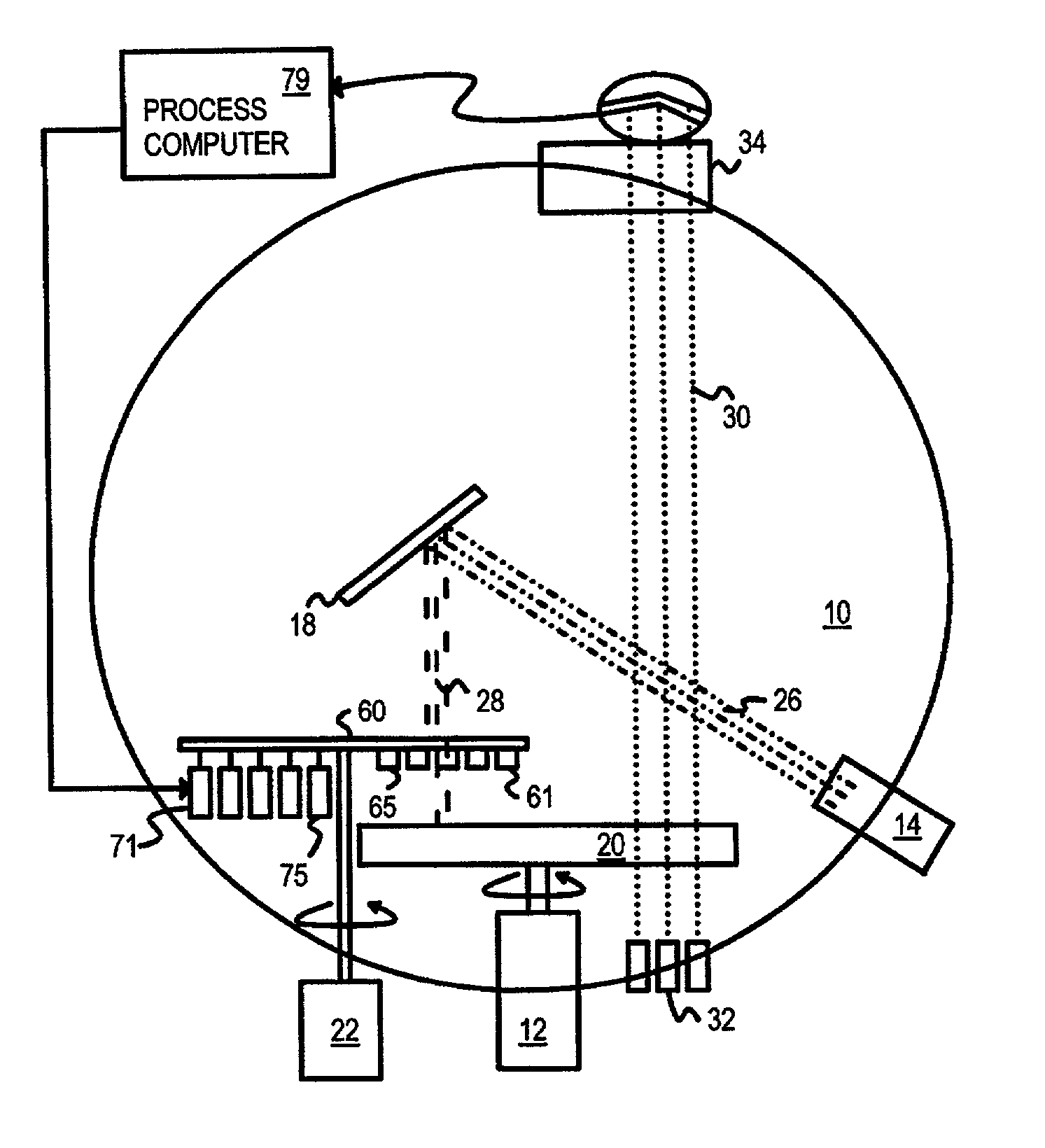
[0047] Several other embodiments are contemplated by the inventors. For example the motors can be replaced with actuators, solenoids, electromagnets, or other electromechanical devices. A single motor could have several gears, linkages, or a clutch mechanism so that it adjusts all fingers, one at a time. A locking mechanism could keep each finger in position once the motor adjusts that finger. Many more adjustable fingers can be used, such as 12 fingers or 20 fingers. The number of fingers can match the number of optical monitoring points, or can be greater of lesser than the number radii monitored. The fingers can be located very close to other fingers or even overlap adjacent fingers to prevent gaps between fingers. One finger can be located higher than adjacent fingers to allow for horizontal overlap yet still have vertical gaps between fingers. The fingers can have a U-shape or other cross-sectional shape rather than be flat plates. The U-shape can face either into or away from ...


PUM

PropertyMeasurementUnit
Thicknessaaaaaaaaaa
Sizeaaaaaaaaaa
Shapeaaaaaaaaaa

Abstract

A vacuum chamber deposits thin films on a substrate by sputtering a target. The beam of atoms or ions from the target is partially blocked by a shadow or adjustable uniformity mask, reducing the deposition rate onto the substrate. The adjustable uniformity mask has several adjustable fingers. The fingers extend or retract to enlarge or reduce the size of the mask. Each finger covers a different annular region or radius of the substrate. The deposition rate at different substrate radii is thus adjustable by the fingers. Several optical beams monitor the film transmittance at different substrate radii. A transmittance profile is continually generated during deposition. As deposition proceeds, radii with a thicker film have their fingers extended to reduce their deposition rate, producing a more uniform film thickness across all radii. Motors extend or retract the individual fingers.

Description

BACKGROUND OF INVENTION[0001] This invention relates to thin-film deposition systems, and more particularly to shadow masks to control the film deposition rate and uniformity.[0002] Electrical and optical systems often rely on devices with thin films. For example, an optical filter may have a hundred layers of films stacked together, each being a quarter of a desired wavelength. These thin films must be deposited with a uniform thickness to prevent unwanted effects, such as a spreading of the wavelength filtered.[0003] These thin films can be deposited in a vacuum chamber using a sputtering or ion beam method. FIG. 1 shows a thin-film deposition chamber using a shadow mask. Chamber 10 is part of a larger film-deposition machine. The air is pumped out of chamber 10 to produce a low-pressure, near-vacuum environment. A substrate 20 is placed in the chamber. One or more layers of thin films are deposited on the upper surface of substrate 20. Substrate 20 is rotated by motor 12 to impro...

Claims


Application Information

Patent Timeline
IPC IPC(8): C23C14/04C23C14/46C23C14/54
CPCC23C14/044C23C14/547C23C14/46
Inventor HSUEH, PAULCHANG, SHYANGSCHIESSER, HANSMA, MICHAELHSU, JACKMA, ABRAHAM C.
Owner SUPER TALENT ELECTRONICS
Why Eureka
Try Eureka