Led lamp

a technology of led lamps and discharge tubes, applied in the direction of discharge tubes/lamp details, luminescent screens, discharge tubes/lamps, etc., to achieve the effect of high intensity outpu

Inactive Publication Date: 2002-10-10
LEDNIUM TECH +1
View PDF3 Cites 28 Cited by
  • Summary
  • Abstract
  • Description
  • Claims
  • Application Information

AI Technical Summary

Benefits of technology

[0005] The present invention seeks to provide an alternative form of LED lamp which can provide high intensity output by utilising a plurality of light emitting diodes, whilst maintaining the appearance of a substantially point source of illumination.
[0014] The curved configuration of the conductors and, in particular, the junctions being arranged on a substantially spheroid imaginary surface provides an advantage that the overall light generated by the lamp will appear to be coming from a generally singular small spherical or point source.

Problems solved by technology

Each chip emits a discrete light pattern, however, and that may be undesirable if the light from the lamp is desired to have an appearance of emitting from a single, point-like light source.

Method used


Image

  • Led lamp
  • Led lamp
  • Led lamp

Examples


Embodiment Construction

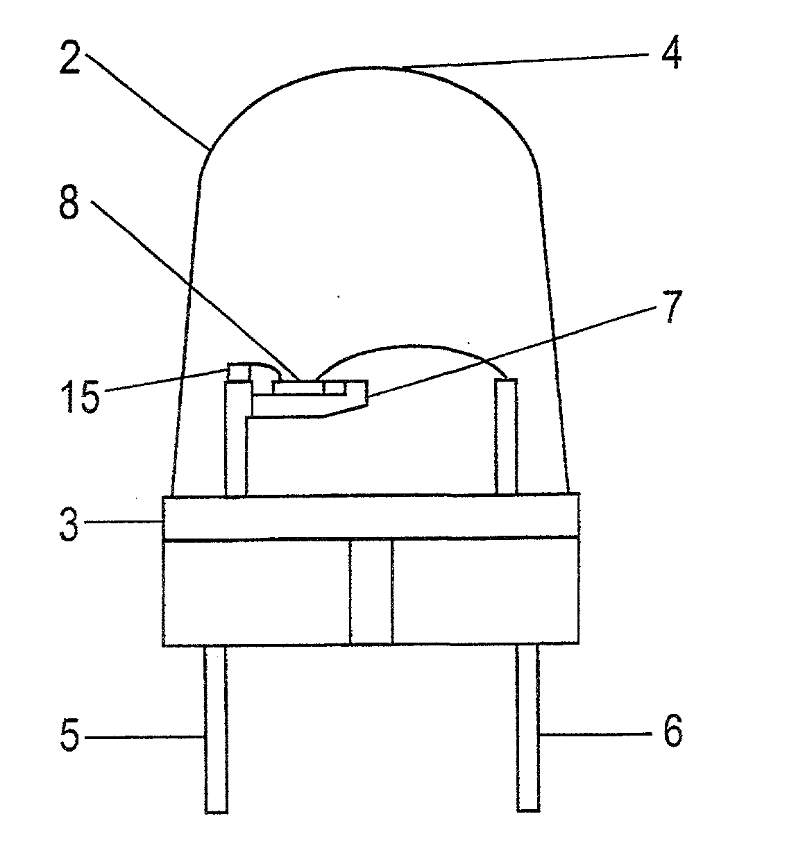
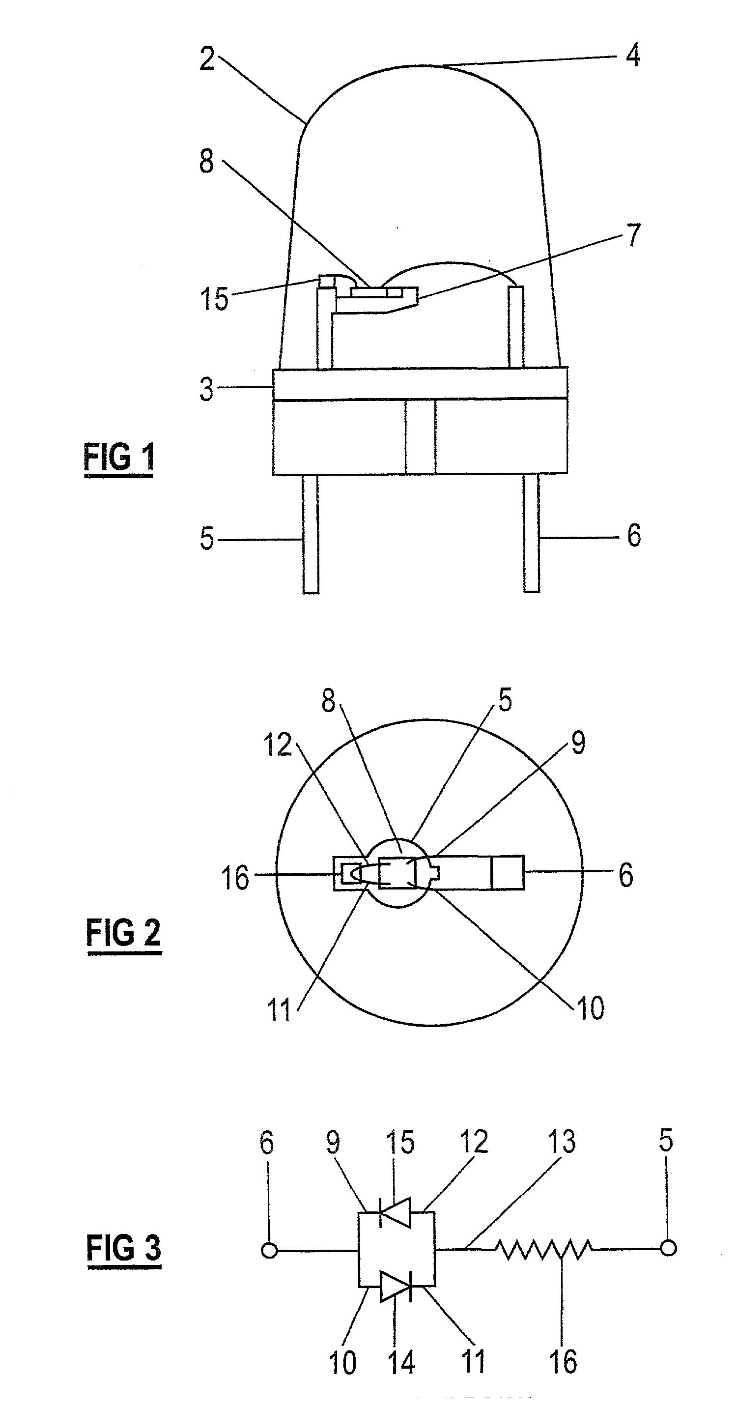
[0035] The lamp 1, as shown in FIG. 1, includes a globe portion 2 with a cylindrical base 3 and a parabolic end 4, configured to enhance illumination output in an axial direction of the lamp. The lamp also includes first and second terminals, which are preferably in the form of conductors 5, 6 which are embedded within the globe portion 2. The lead 5 has a support platform 7 to which is mounted an integrated circuit wafer 8. In the example given, the wafer includes two junctions which are arranged substantially adjacent each other so that a common layer of fluorescent material, such as a phosphor layer, may be applied over both junctions. Intermediate conductors 9 to 12 electrically couple the junctions to the respective terminals 5, 6 so that the LED junctions 14, 15 are arranged in reverse polarity, as indicated in the circuit diagram FIG. 3. A resistive element 16 is provided between a further conductor 13 (connecting the intermediate conductors 11 and 12) and the lead 5.

[0036] T...


PUM


Abstract

A lamp including a plurality of semi-conductor light emitting junctions with a common layer of fluorescent material arranged thereover. The invention provides a lamp including a plurality of light emitting junctions mounted to at least one curved conductor so as to adopt a three-dimensional array.

Description

[0001] The present invention relates to an LED lamp.[0002] U.S. Pat. No. 5,998,925 discloses a light emitting device which comprises a semi-conductor light emitting layer embedded in a transparent globe. A fluorescent material covers the semi-conductor layer to receive the emitted light for transmission at a different wavelength, i.e. in a predetermined colour.[0003] To increase the intensity of the light output, additional semi-conductor devices may be added, such as shown in U.S. Pat. No. 5,289,082, which discloses an LED lamp having a plurality of semi-conductive chips mounted in a translucent body. Each chip emits a discrete light pattern, however, and that may be undesirable if the light from the lamp is desired to have an appearance of emitting from a single, point-like light source. In U.S. Pat. No. 5,289,082, the discrete light outputs are combined and focussed, by specific shaping of the body to produce an overall light output having a required illumination pattern.[0004] G...

Claims


Application Information

Patent Timeline
Patent Type & Authority Applications(United States)
IPC IPC(8): F21Y101/02F21V5/04H01L25/075H01L33/50
CPCH01L25/0753H01L33/50H01L33/62H01L2224/48091Y10S362/80H01L2224/48247H01L2924/00014
Inventor JEGANATHAN, BALUMONTAGNAT, JOHN ALBERT
Owner LEDNIUM TECH
Why Eureka
Try Eureka