

Image shake correcting device
a technology of shake sensor and shake sensor, which is applied in the direction of camera body details, instruments, printing, etc., can solve the problems of shake sensor error output, proposal, and increase power consumption
- Summary
- Abstract
- Description
- Claims
- Application Information
AI Technical Summary
Problems solved by technology
Method used
Image

Examples
first embodiment
[0025] the present invention will be described below with reference to the drawings.
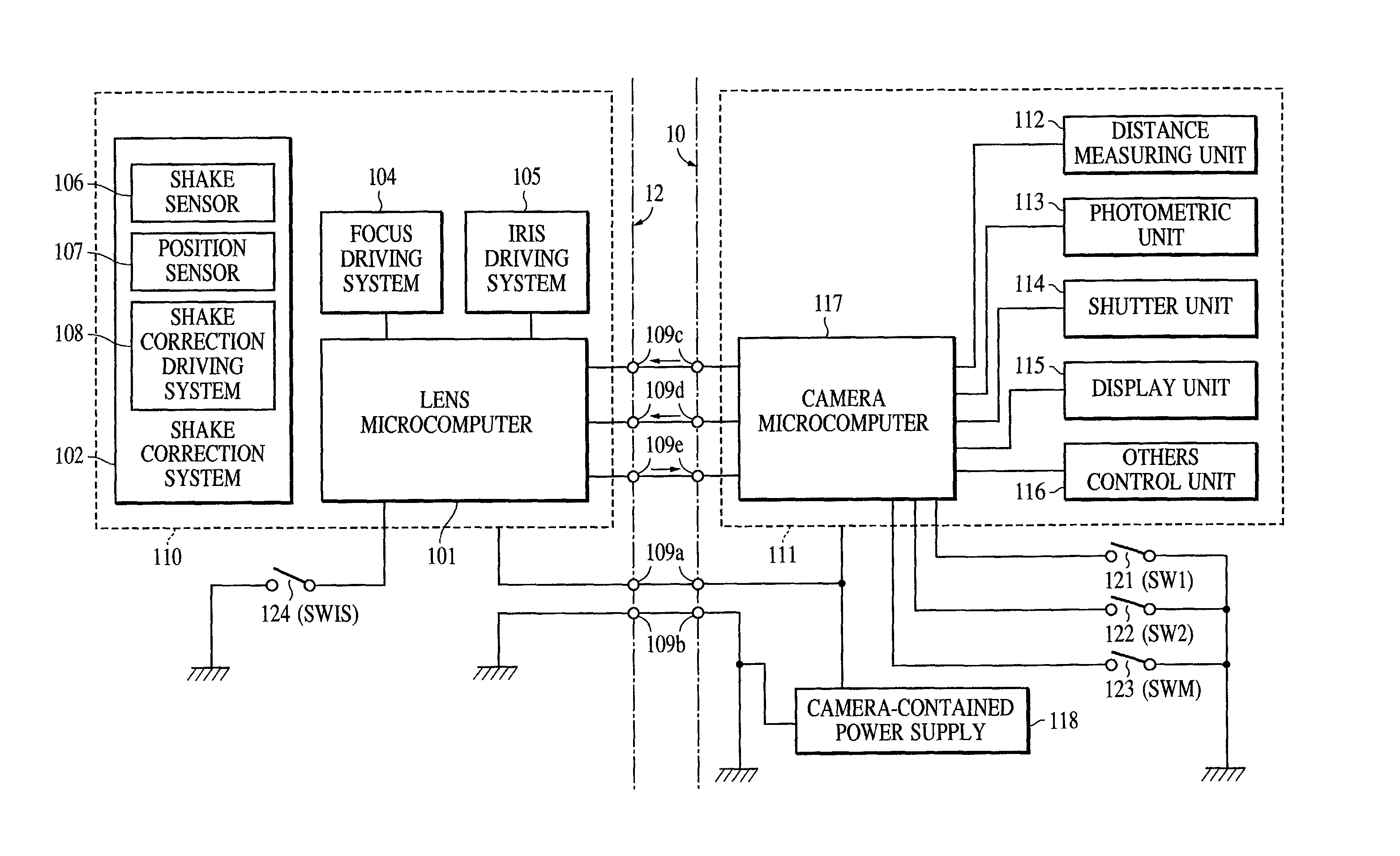
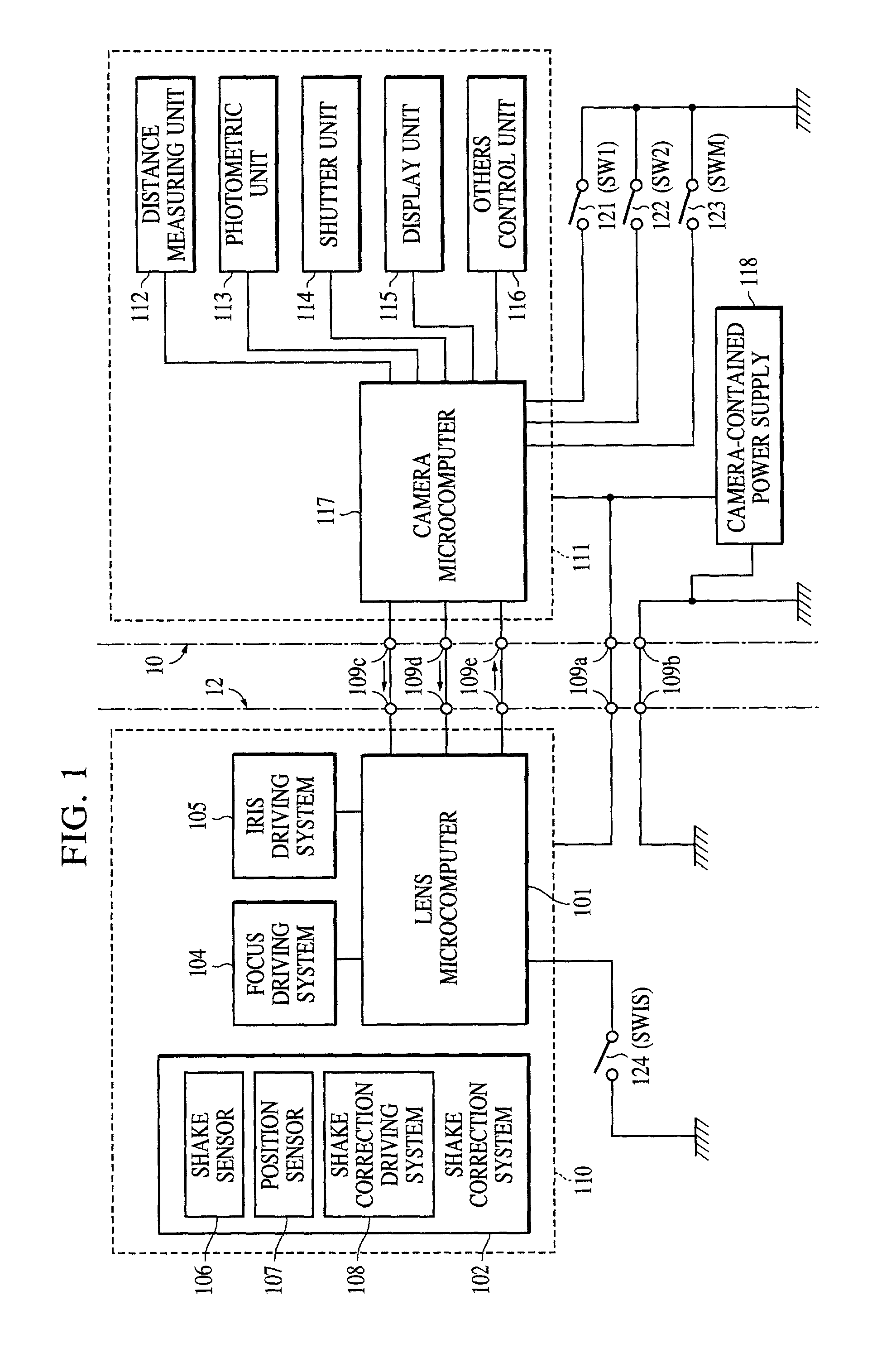
[0026] FIG. 10 shows a schematic construction of a camera system comprising a camera body and an interchangeable lens according to the first embodiment of the present invention. In an illustrated condition, an interchangeable lens 143 provided with an image shake correcting device is attached to a single-lens reflex camera body 131.
[0027] The camera body 131 includes a pentaprism 132, and a semitransparent main mirror 133, fixed at its upper end, for passing a part of incident light through it toward a film surface 134 and reflecting the remaining part of incident light toward a finder optical system. Numeral 135 denotes an auxiliary mirror for introducing light to a distance-measuring sensor 136. The auxiliary mirror 135 is retracted to the lower side of a mirror box during an exposure. Numeral 137 denotes an eyepiece lens and 138 denotes a shutter unit.
[0028] The interchangeable lens 143 includes a...
second embodiment
[0066] Next, a single-lens reflex camera including an image shake correcting device according to a second embodiment of the present invention will be described.
[0067] In the above first embodiment, when a support member is detected, the characteristic of the image shake correction control is changed over depending on the shutter speed for each of both the first control direction, e.g., the pitch direction, and the second control direction, e.g., the yaw direction. In practice, however, shake generated upon an impact applied from the quick return mirror uniquely depends on a mirror mechanism of the camera, and is restricted substantially only in one direction.
[0068] Accordingly, it is preferable that when a support member is detected, image shake correction control as described in connection with the above first embodiment is performed only for the direction in which the shake attributable to the quick return mirror occurs, and image shake correction control for keeping fixed the off...
third embodiment
[0075] Next, a single-lens reflex camera including an image shake correcting device according to a third embodiment of the present invention will be described.
[0076] The above first and second embodiments are premised on the fact that the mirror is moved up in the exposure operation. In some of cameras, however, no mirror is moved up in the exposure operation. In such a camera, because there occurs no shake attributable to an impact of the mirror-up operation, it is not required to perform image shake correction control for correcting the camera shake of a high-frequency and small amplitude. In other words, even when a support member is detected, there is no need for changing over the mode of the image shake correction control. Accordingly, it is preferable that when a support member is detected, image shake correction control is performed in the same manner as described in the first and second embodiments on a camera including a mirror which is moved up in the exposure operation, a...
PUM
 Abstract
Description
Claims
Application Information