Method, system, and apparatus for binary traversal of a tag population

a technology of radio frequency identification and population, applied in the direction of near-field systems using receivers, burglar alarm mechanical actuation, instruments, etc., can solve the problems of large power consumption of available tags, inefficient and expensive tag power schemes, and large amount of available tags

Active Publication Date: 2002-10-17
SYMBOL TECH LLC
View PDF88 Cites 95 Cited by
  • Summary
  • Abstract
  • Description
  • Claims
  • Application Information

AI Technical Summary

Problems solved by technology

For instance, currently available tags are relatively expensive.
Furthermore, currently available tags consume large amounts of power.
Currently available tag power schemes, which include individually tag-included batteries, are inefficient and expensive.
These inefficient power schemes also lead to reduced ranges over which readers may communicate with tags in a wireless fashion.
Still further, currently available readers and tags use inefficient interrogation protocols.
These inefficient protocols slow the rate at which a large number of tags may be interrogated.
Conventional algorithms interrogate RFID tags with highly complex algorithms that are less efficient.
Furthermore, the use of conventional algorithms often involves two or more RF transmissions colliding.
Collision resolution consumes time without conveying data, and mandates complexity in algorithms, circuit design, and transistor count.
However, this may also introduce a burden on the implementation to add functionality, memory, processing power, etc., in order to present information to the highest OSI model layers.
This may result in an orientation sensitivity for a tag an

Method used


Image

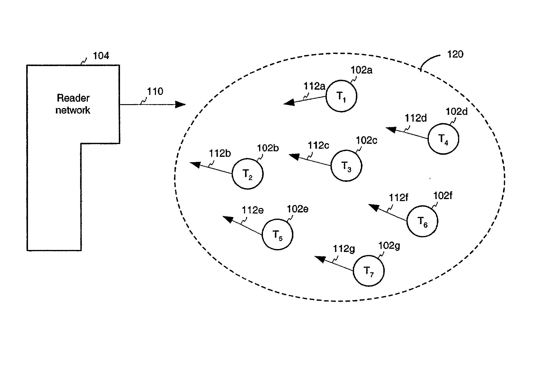
  • Method, system, and apparatus for binary traversal of a tag population
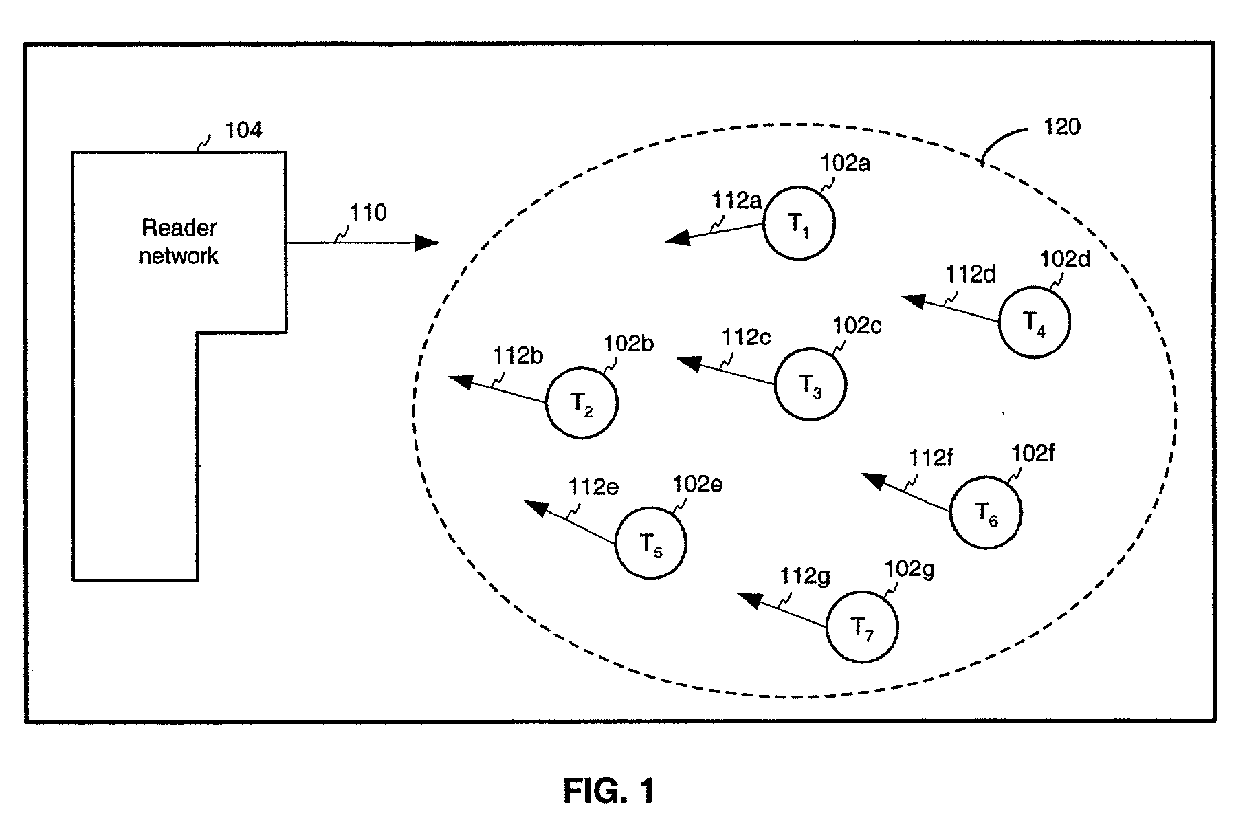
  • Method, system, and apparatus for binary traversal of a tag population
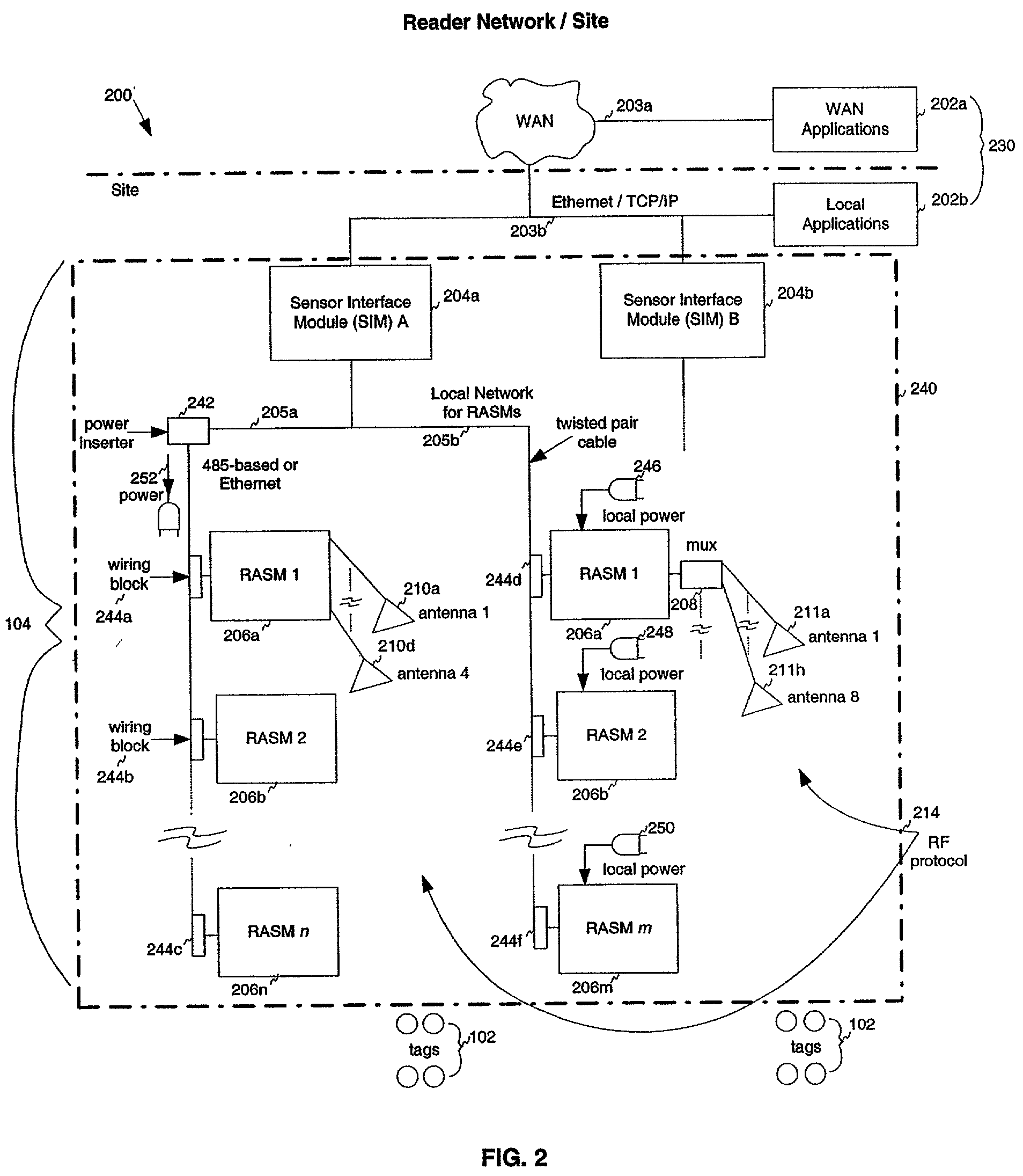
  • Method, system, and apparatus for binary traversal of a tag population

Examples


Embodiment Construction

[0325] FIG. 17A shows a flowchart illustrating operation of a tag 102 in superposition state 1210. As shown in FIG. 17A, operation begins with step 1702. In step 1702, tag 102 is in dormant state 1202.

[0326] In step 1704, tag 102 receives a master reset signal from reader network 104. Upon receipt of this signal, tag 102 transitions from dormant state 1202 to calibration state 1204.

[0327] In step 1706, tag 102 is synchronized with reader network 104. Accordingly, oscillator calibration and data calibration procedures occur, that are further described below. After tag 102 becomes synchronized with reader network 104, it enters command state 1206.

[0328] In step 1708, tag 102 receives a command from reader network 104 that causes tag 102 to transition to superposition state 1210. As described above, the command may be a one or more bits, such as a single bit logical "1" symbol 402.

[0329] In step 1710, tag 102 designates an initial bit of its identification number for transmission as a ...


PUM


Abstract

A method, system, and apparatus for interrogating a radio frequency identification (RFID) tag population are described. Tags are interrogated by a reader. The reader and tags engage in communication according to binary traversal algorithms, where single bit data symbols are exchanged between the reader and tags. Furthermore, a reader implicitly controls the operating state of every tag in the tag population by transmitting a single data symbol. Bit patterns may be collected from the tags by the reader, using a variety of interrogation techniques. In a general interrogation, the reader exchanges symbols with the tag population to interrogate the entire tag population. In a specific interrogation, a reader exchanges symbols with the tag population to target a particular tag identification number. Tags may also be placed in a superposition state by the reader, where they respond whenever a received data symbol matches the next bit of their identification number.

Description

[0001] This application claims the benefit of U.S. Provisional Application No. 60 / 267,713, filed Feb. 12, 2001, which is herein incorporated by reference in its entirety.[0002] 1. Field of the Invention[0003] The present invention relates generally to radio frequency identification (RFID) tags.[0004] 2. Description of the Related Art[0005] Many product-related and service-related industries entail the use and / or sale of large numbers of useful items. In such industries, it may be advantageous to have the ability to monitor the items that are located within a particular range. For example, within a particular store, it may be desirable to determine the presence of inventory items located on the shelf, and that are otherwise located in the store.[0006] A device known as an RFID "tag" may be affixed to each item that is to be monitored. The presence of a tag, and therefore the presence of the item to which the tag is affixed, may be checked and monitored by devices known as "readers." ...

Claims


Application Information

Patent Timeline
IPC IPC(8): G06K7/00G06K17/00G06K19/07G11C5/14H04B1/59H04B5/02H04L7/033
CPCG06K7/0008G06K7/10039G06K7/10069G06K7/10108G06K7/10356G06K17/00H04L7/0331G06K19/0723G06K19/07749G06K19/07767G08B13/2485G11C5/142G06K19/0713
Inventor SHANKS, WAYNE E.POWELL, KEVIN J.BANDY, WILLIAM R.ARNESON, MICHAEL R.
Owner SYMBOL TECH LLC
Why Eureka
Try Eureka