
System and method for signal matching and characterization

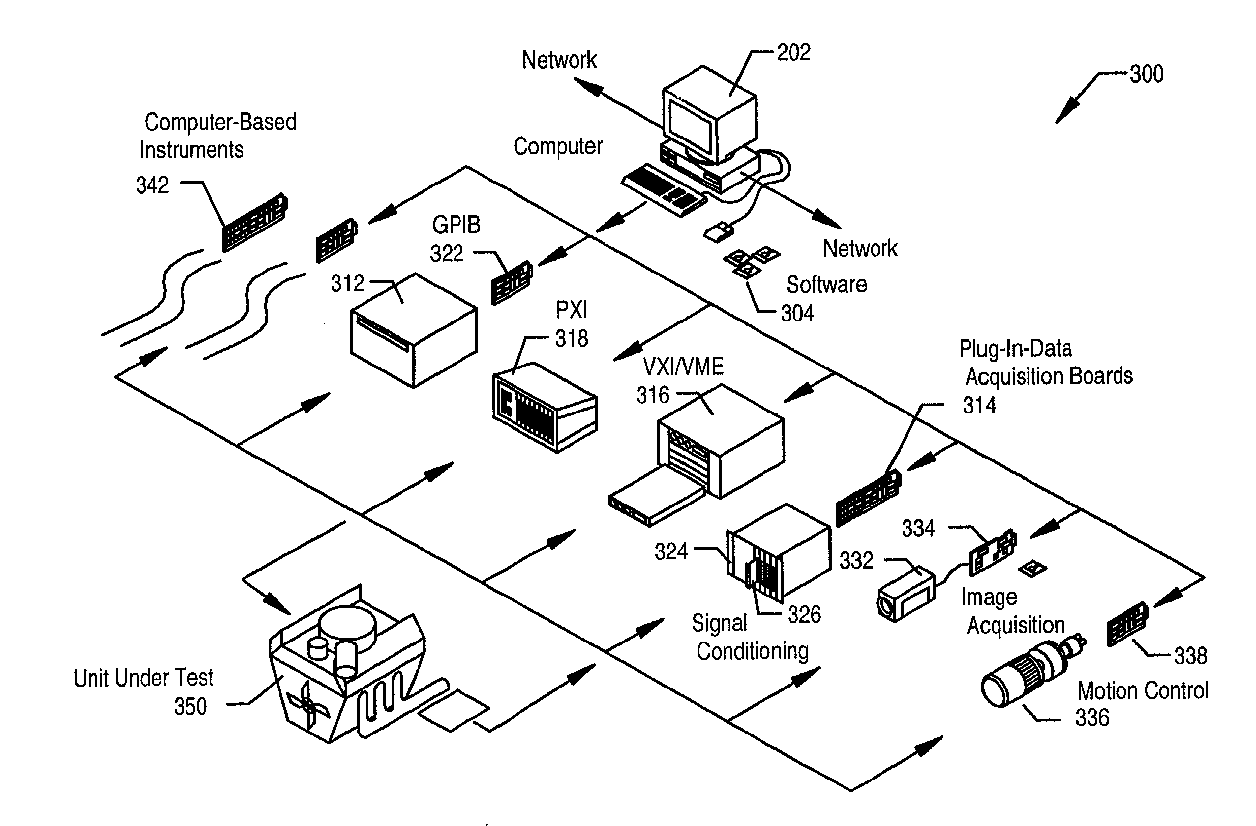
a signal matching and signal technology, applied in the field of system and method for signal matching and characterization, can solve the problems of inability to use and the difficulty in matching or characterizing the received signal, and the inability to determine fast, the method described in figs. 1a and 1b cannot be used

Inactive Publication Date: 2002-10-17
NATIONAL INSTRUMENTS
View PDF7 Cites 91 Cited by
  • Summary
  • Abstract
  • Description
  • Claims
  • Application Information

AI Technical Summary

Problems solved by technology

The presence of noise or other distortions in the received signal complicates the task of matching or characterizing the received signal.
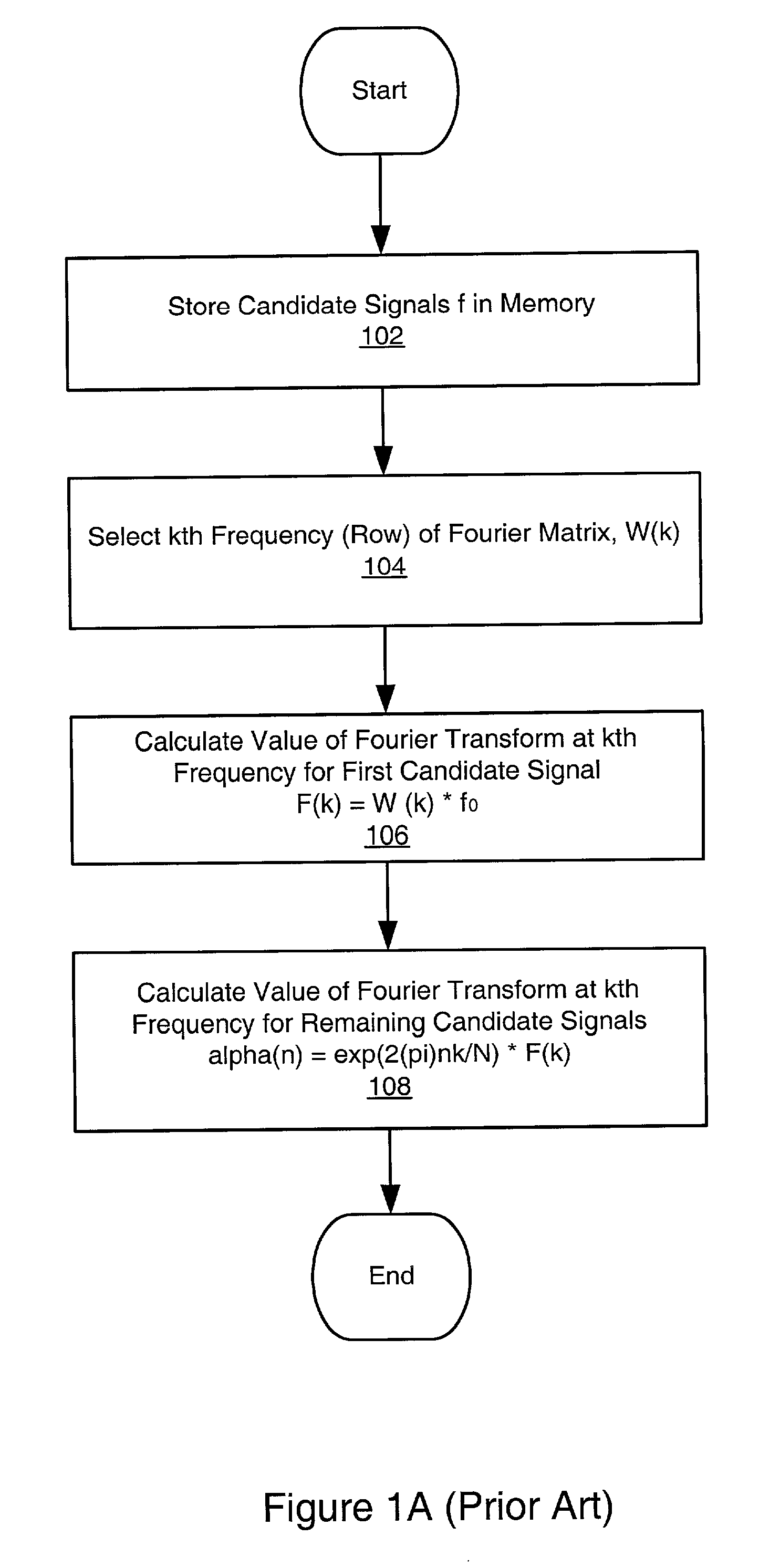
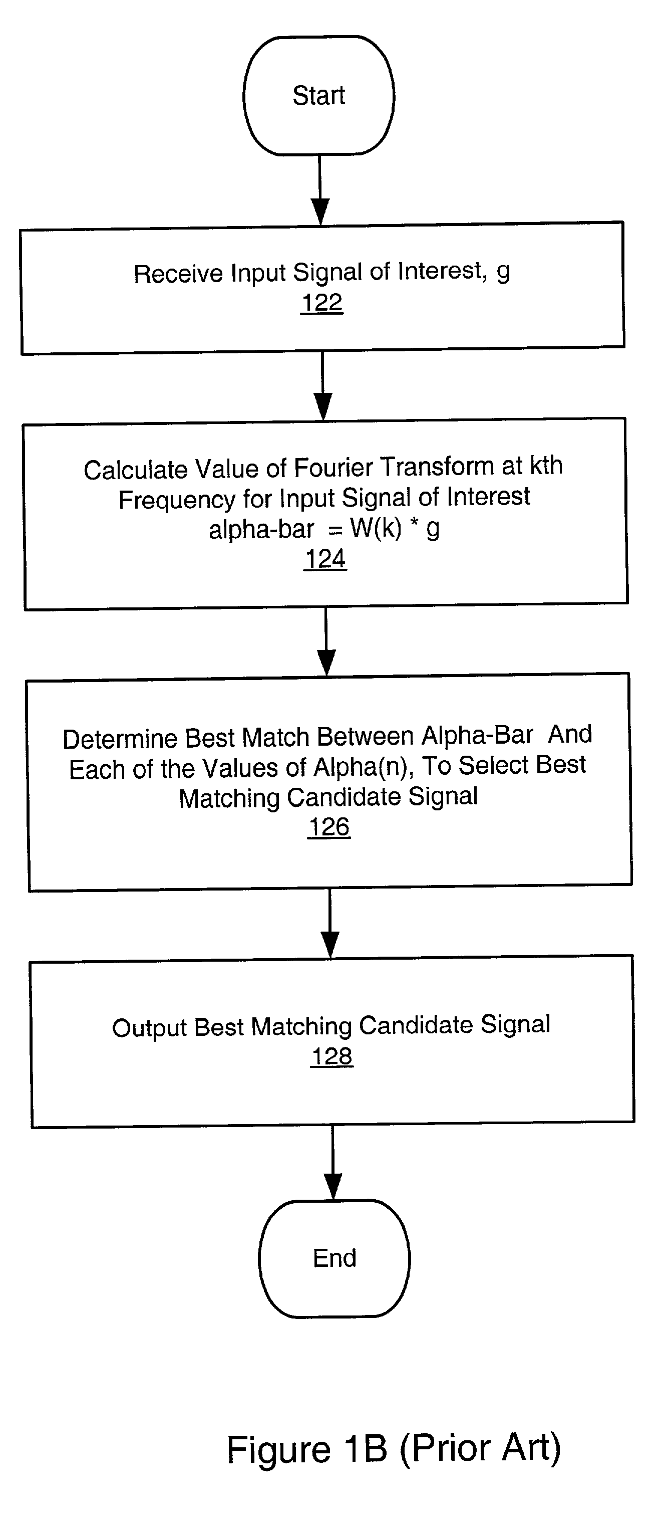
However, when one or more of the signals in the set of candidate signals are not shifted versions of each other, e.g., are uncorrelated, then the method described in FIGS. 1A and 1B cannot be used.
The problem of attempting to match a received input signal of interest with one of a set of candidate or template signals, wherein two or more of the signals comprised in the set of candidate or template signals are uncorrelated with each other, arises in many diverse fields.
Further, there are no fast techniques available which can be used to determine a closest match between an input signal of interest and a set of uncorrelated signals.
This information may be in the form of a digital signal and may contain noise as well.
This is especially true with wireless communications because any number of signals may be present simultaneously in the same medium (the airways), including noise from sources as diverse as electrical equipment and solar winds.
Machine vision systems such as described above are often required to process the image data in or near real-time, which places severe constraints on the performance of pattern matching methods.
As described above, the problem is to determine the best match between the input signal of interest g and one signal from the set of candidate signals.
For example, if the received input signal of interest is not represented among the set of candidate signals, a "best match" may still be found, but which, after further analysis, may be determined to be an inappropriate match for the input signal.
The maximum value of C indicates the position where w best matches f. Since the underlying mechanism for correlation is based on a series of multiplication operations, the correlation process is time consuming.
The basic normalized cross correlation operation does not meet speed requirements for many applications.
Extending correlation to detect patterns that are invariant to scale changes and rotation is difficult.
Approaches based on multidimensional Discrete Fourier Transforms and Principal Component Analysis have been proposed, but are generally considered to be inadequate, due to the slowness of the learning phase and requirements for non-integer operations.
Images typically contain much redundant information.
It is noted that for unbalanced sets of points this correlator has linear complexity.

Method used


Image

  • System and method for signal matching and characterization
  • System and method for signal matching and characterization
  • System and method for signal matching and characterization

Examples


Embodiment Construction

[0196] Assume we are given the following matrix 9 B = ( b 11 b 12 b 21 b 22 b 21 b 22 b 11 b 12 b 31 b 32 b 41 b 42 b 41 b 42 b 31 b 32 ) with ( is very small ) b 12 =( 1 + i 2 )b 31 + ( 1 - i 2 )b 41 b 22 =( 1 - i 2 )b 31 + ( 1 + i 2 )b 41 b 32 =( 1 + i 2 )b 11 + ( 1 - i 2 )b 21 b 42 =( 1 - i 2 ) b 11 + ( 1 + i 2 )b 21 b 21 = b 11 + b 41 = b 31

[0197] The two free parameters b.sub.11 and b.sub.31 are chosen in such a manner that B is regular. It can be shown that 10 A =B 'B - 1 = 0.5 (0 01 + i 1 - i 0 01 - i 1 + i 1 + i 1 - i0 0 1 - i 1 + i0 0)

[0198] which results in the Walsh-matrix 11 X B = 0.5 (1 1 1 1 1- 11- 1 1 1- 1 - 1 1- 1 - 11)

[0199] Example Applications

[0200] As mentioned above, there are many real-world applications for methods of pattern or signal matching. The following examples of pattern matching applications are intended to be illustrative, and are not intended to limit the scope or domain of applicability of the present method.

[0201] As noted above, an exemplary appl...


PUM


Abstract

A system and method for selecting a best match of a received input signal from a set of candidate signals, wherein two or more of the candidate signals are uncorrelated. In a preprocessing phase a unified signal transform (UST) is determined from the candidate signals. The UST converts each candidate signal to a generalized frequency domain. The UST is applied at a generalized frequency to each candidate signal to calculate corresponding generalized frequency component values (GFCVs) for each candidate signal. At runtime, the input signal of interest is received, and the UST is applied at the generalized frequency to the input signal of interest to calculate a corresponding GFCV. The best match is determined between the GFCV of the input signal of interest and the GFCVs of each of the set of candidate signals. Finally, information indicating the best match candidate signal from the set of candidate signals is output.

Description

[0001] The present invention relates to the field of signal processing, and more particularly to pattern matching and signal characterization.DESCRIPTION OF THE RELATED ART[0002] A great variety of systems may be characterized by the property that they receive a signal and attempt to match the received signal to one of a series of candidate or template signals. Such signal or pattern matching is common in diverse fields such as telecommunications, wireless telecommunications, radar, machine vision and control, system automation, manufacturing, quality control, acoustics, optics, measurement, filtering, data analysis, and others. Signal types may include 1-dimensional (1-D) signals, 2-D signals, such as images, as well as 3-D and higher dimensional data sets or signals. Signals may also be either analog or digital signals.[0003] The presence of noise or other distortions in the received signal complicates the task of matching or characterizing the received signal. In many systems, th...

Claims


Application Information

Patent Timeline
Patent Type & Authority Applications(United States)
IPC IPC(8): G06F17/15G06V10/42
CPCG06F17/15G06K9/00496G06K9/6203G06K9/522G06K9/52G06V10/431G06V10/42G06V10/7515G06F2218/00
Inventor RAJAGOPAL, RAMWENZEL, LOTHARNAIR, DINESHSCHMIDT, DARREN
Owner NATIONAL INSTRUMENTS
Learn More