Fiber optic power source for an electroencephalograph acquisition apparatus

Inactive Publication Date: 2002-10-31
PHYSIOMETRIX
View PDF5 Cites 21 Cited by
  • Summary
  • Abstract
  • Description
  • Claims
  • Application Information

AI Technical Summary

Benefits of technology

0010] The reusable appliance of this invention comprises a micro-miniature, micropower, low noise multi-channel data-acquisition system powered by a fiber optic illuminator and photovoltaic cell, thus

Problems solved by technology

That application describes, among other things, the signals which will be gathered from the patient's head and as well the information which will be produced for the anesthesia practitioner but does not disclose the most effective way of acquiring the raw signals from the patient's head.
Signal acquisition for patient monitoring use in the OR and ICU presents a number of design challenges that can and will effect the overall acceptance of the product based on its cost, ease of use and performance.
Although designed for "ease of use," a 7 lead device is inherently more difficult to use and expensive than, for example, a 3-lead frontal array.
Nevertheless, such disposable attachments cost on the order of two dollars to manufacture
In addition, the harsh EMI environment of the operating room challenges a monitoring system, since electrosurgical devices produce signals up to 1 billion times greater in amplitude than that of the EEG.
T

Method used


Image

  • Fiber optic power source for an electroencephalograph acquisition apparatus
  • Fiber optic power source for an electroencephalograph acquisition apparatus
  • Fiber optic power source for an electroencephalograph acquisition apparatus

Examples


Embodiment Construction

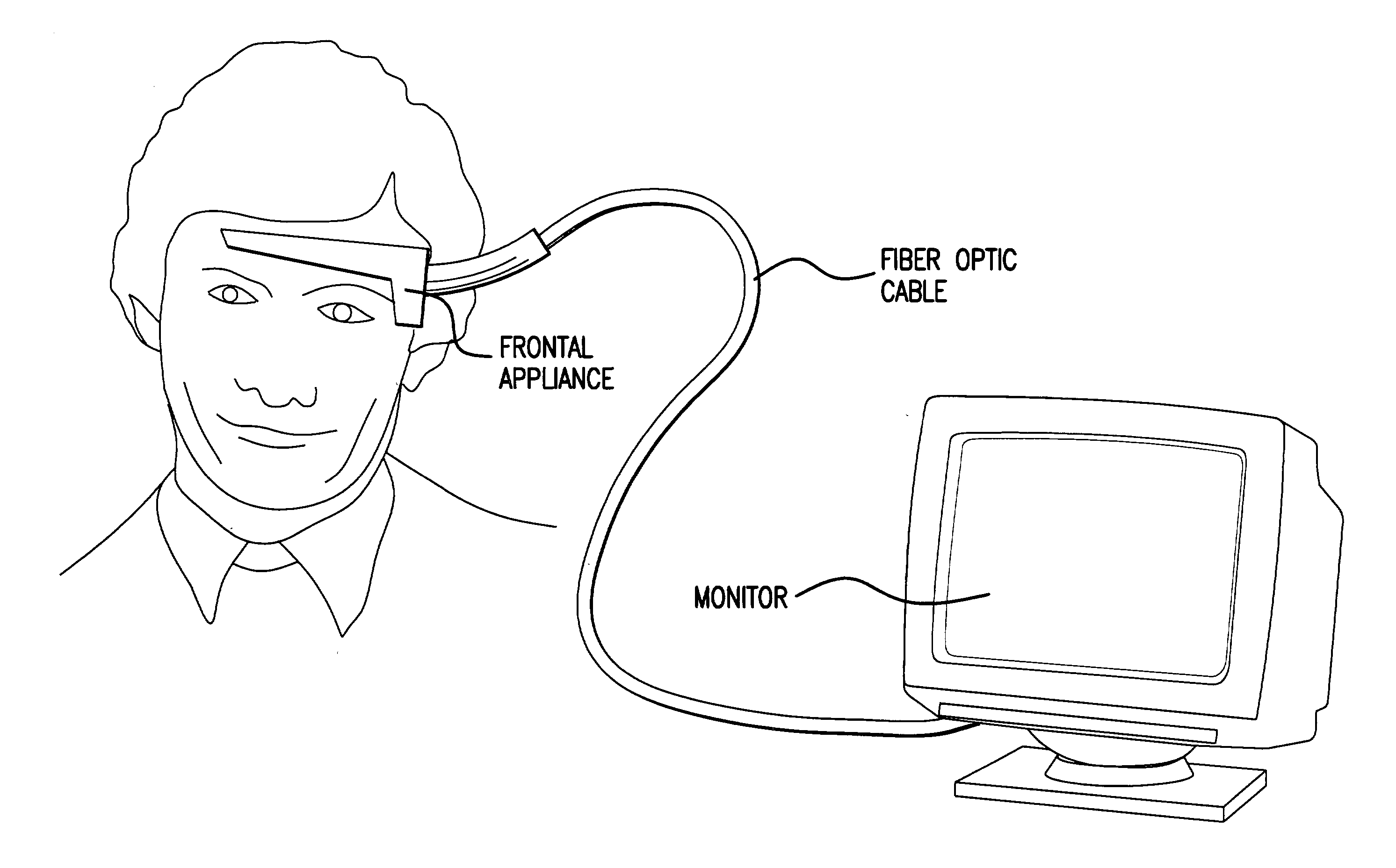
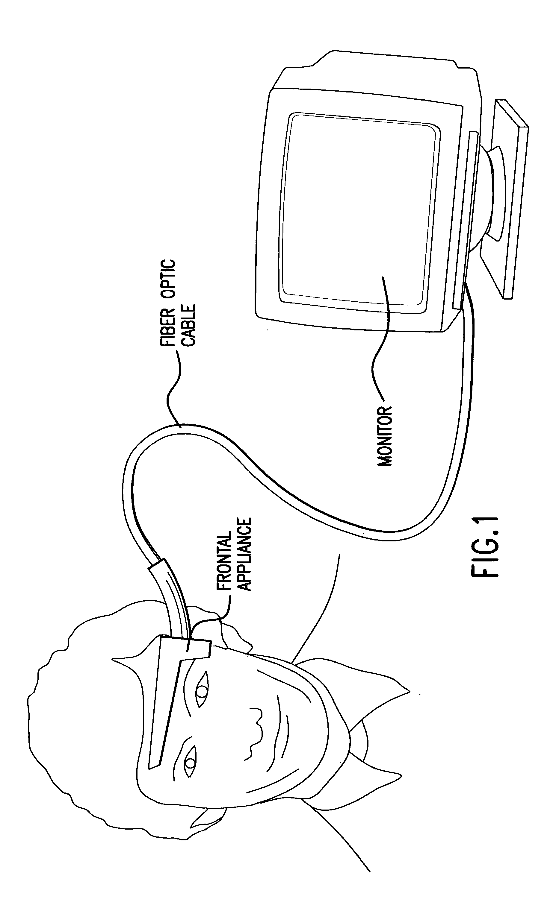
[0015] As shown in FIG. 1, the electronics at the patient end of the cable is housed in a semi-rigid enclosure. Internal circuitry is wrapped in a flexible conductive Faraday shield layer connected to the amplifier's signal ground. The circuit layout is designed such that the contact patch for each of the signal electrodes is incorporated at the intended recording site for the Frontal Array signal montage. These patches are the only portions of the electronics external to the shield layer.

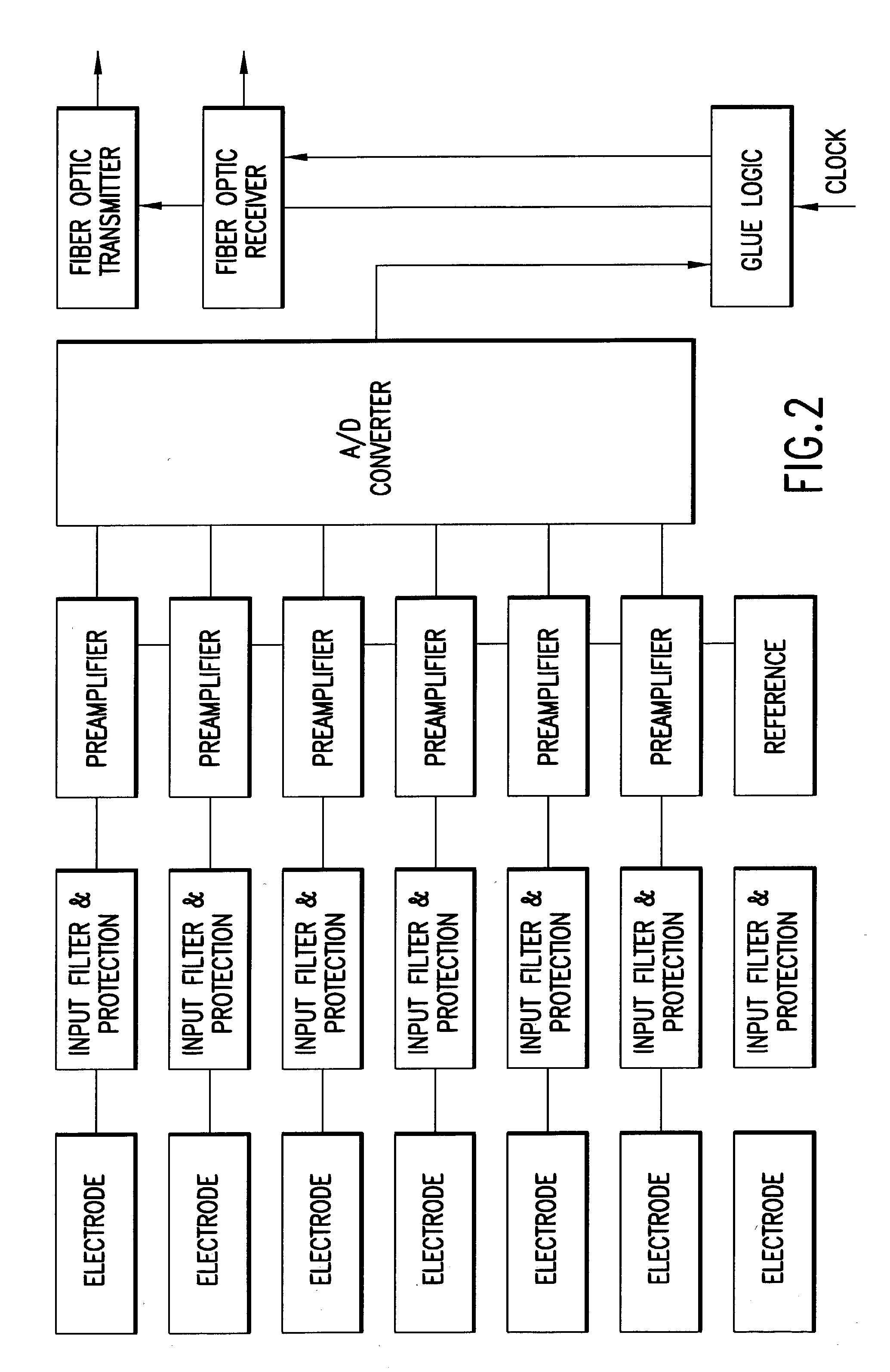
[0016] A system diagram is shown in FIG. 2. Each of the signals is filtered and voltage limited through the unique application of a voltage limiter / capacitor at each of the amplifier's signal inputs. This device is the first leg of a multistage R-C-R-C filter optimized for the EEG signal bandwidth. This device also provides protection to the patient and EEG amplifier meeting IEC601-2-26 "Particular requirements for the safety of electroencephalographs" when used with defibrillators in accordance wi...


PUM


Abstract

A reusable appliance for acquisition from a patient of EEG signals comprising a micro-miniature, micro-power, low noise multi-channel data-acquisition system powered by a fiber optic illuminator and photovoltaic cell thus eliminating the need for inductively coupled power converters. The appliance also uses disposable EEG electrodes which are similar in size and very low cost.

Description

[0001] This application claims the benefit of priority under co-pending United States Provisional Application No. 60 / 161,644, filed Oct. 27, 1999.FIELD OF THE INVENTION[0002] The current invention relates to the field of medical anesthesia. More particularly it relates to the field of electronic monitoring of a patient undergoing anesthesia, especially for use during and after surgical operations. The invention more specifically relates to the device used to acquire electrical electroencephalograph (EEG) signals used to monitor a patient's state of awareness, more specifically still to the device comprising and obtaining electroencephalograph signals from one or more electrodes attached to the patient's head.BACKGROUND OF THE INVENTION[0003] Traditionally in the administration of anesthesia it has been the practice for an anesthesiologist to use only clinical signs from the patient to estimate the depth of the patient's anesthesia before and during surgical procedures requiring anes...

Claims


Application Information

Patent Timeline
IPC IPC(8): A61B5/0476A61N1/04
CPCA61B5/0476A61B2562/223A61B5/7217A61N1/0492A61N1/0476A61B5/369A61B5/386
Inventor MARRO, DOMINIC P.
Owner PHYSIOMETRIX
Why Eureka
Try Eureka