
Method and device for mismatch recognition in a vehicle radar system or a vehicle sensor system

a vehicle radar system and mismatch recognition technology, applied in the direction of reradiation, pedestrian/occupant safety arrangement, instruments, etc., can solve the problems of inability to always be precisely determined, difficult to measure, and small offsets and far away detection objects are necessary for exact determination or correction

Inactive Publication Date: 2002-11-07
ROBERT BOSCH GMBH
View PDF0 Cites 14 Cited by
  • Summary
  • Abstract
  • Description
  • Claims
  • Application Information

AI Technical Summary

Benefits of technology

[0007] An advantageous further refinement of the method according to the present invention provides that a correction value (Psi_null_punkt) for yaw rate (Psi_m_punkt) is determined on the basis of relative angle (alpha_m), correction value (alpha_null), relative distance (d_m), relative velocity (d_m_punkt), the vehicle's own velocity (v_F), and a yaw rate (Psi_m_punkt) supplied by a yaw-rate sensor. In other words: The measured yaw rate value supplied by any yaw-rate sensor can be corrected with the aid of the measured value supplied by the motor vehicle radar system. A reliable, quick determination of the yaw rate of the motor vehicle is possible in this manner.
[0008] In a particularly advantageous further refinement of the method according to the present invention, a yaw rate (Psi_punkt) of the motor vehicle is determined on the basis of relative angle (alpha_m), correction value (alpha_null), relative distance (d_m), relative velocity (d_m_punkt), and the vehicle's own velocity (v_F). As a result of the method according to the present invention, it is possible with the aid of the data supplied by a motor vehicle radar system to quickly and reliably determine the yaw rate of the motor vehicle without a conventional yaw-rate sensor having to be present in the motor vehicle.
[0009] The great advantage of the method according to the present invention and of the device according to the present invention is that the offset determination of the measured angle value and the measured yaw rate value as well as the yaw rate determination can be carried out while the vehicle is in operation "online." Thus, a shifting offset of the measured angle value and of the measured yaw rate value can be permanently and correctly compensated for even while the motor vehicle is in operation. It is not necessary to separately measure the sensors, e.g. in a workshop. In this context, the method according to the present invention is not based on an averaging of data ascertained by the motor vehicle radar system from stationary objects, but on a calculation having the data ascertained from the stationary objects as a basis. A further decided advantage is that the calculation can be performed in any driving situation, independently of whether the motor vehicle is moving in a straight line or is cornering.DESCRIPTION OF EXEMPLARY EMBODIMENTS

Problems solved by technology

The disadvantage of this method is that small offsets and far away detection objects are necessary for exact determination or correction.
However, in radar applications, distant objects, in particular, are "weak targets," which are difficult to measure, and whose position in the transverse direction to the vehicle in question cannot always be precisely determined due to the limited angular resolution of the radar system.
For the same reason (limited angular resolution), the determination of transverse velocities of detected objects, in particular at greater distances, is also faulty.
The disadvantage of the method is that it is necessary to analyze the determined radial distance of the detected object to the motor vehicle in question into X and Y position coordinates.
Typically, the angle of the detected object goes into such an analysis, the angle not being able to be determined in a particularly precise manner in the case of a system functioning on a laser or radar basis since a limited angle resolution must be used as a baseline.
The disadvantage of this method is that the X and Y components of the relative velocity vector, which, as previously stated, cannot be determined in a particularly precise manner, are necessary for an analysis of the relative velocity vectors.

Method used


Image

  • Method and device for mismatch recognition in a vehicle radar system or a vehicle sensor system
  • Method and device for mismatch recognition in a vehicle radar system or a vehicle sensor system
  • Method and device for mismatch recognition in a vehicle radar system or a vehicle sensor system

Examples


Embodiment Construction

[0010] Exemplary embodiments of the method according to the present invention and the device for detecting misalignment in a motor vehicle radar system according to the present invention are explained in light of the drawings in the following.

[0011] The figures show:

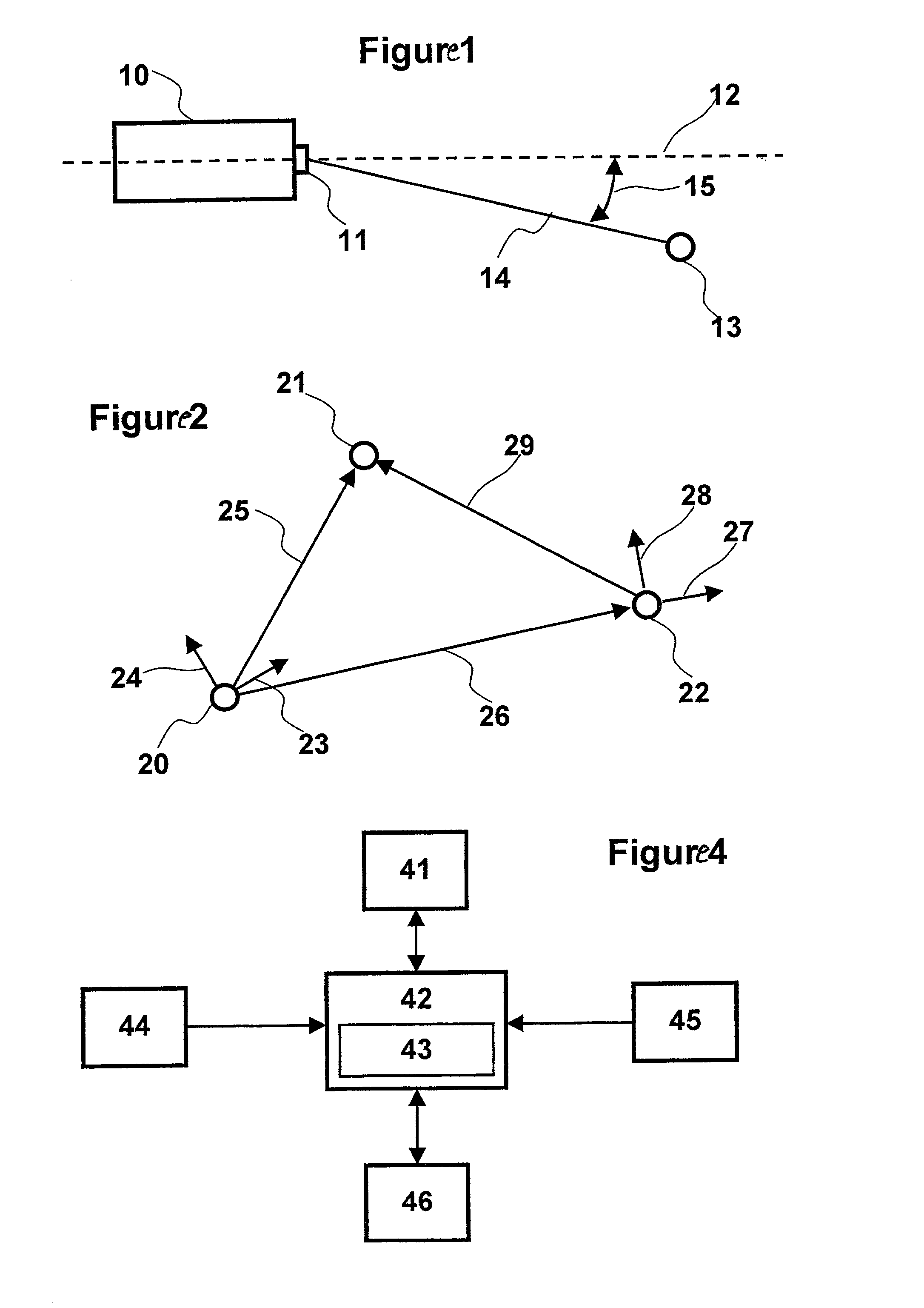
[0012] FIG. 1 shows a motor vehicle detecting a stationary object;

[0013] FIG. 2 shows a representation of the coordinate systems that must be taken into consideration for the determination of the misalignment;

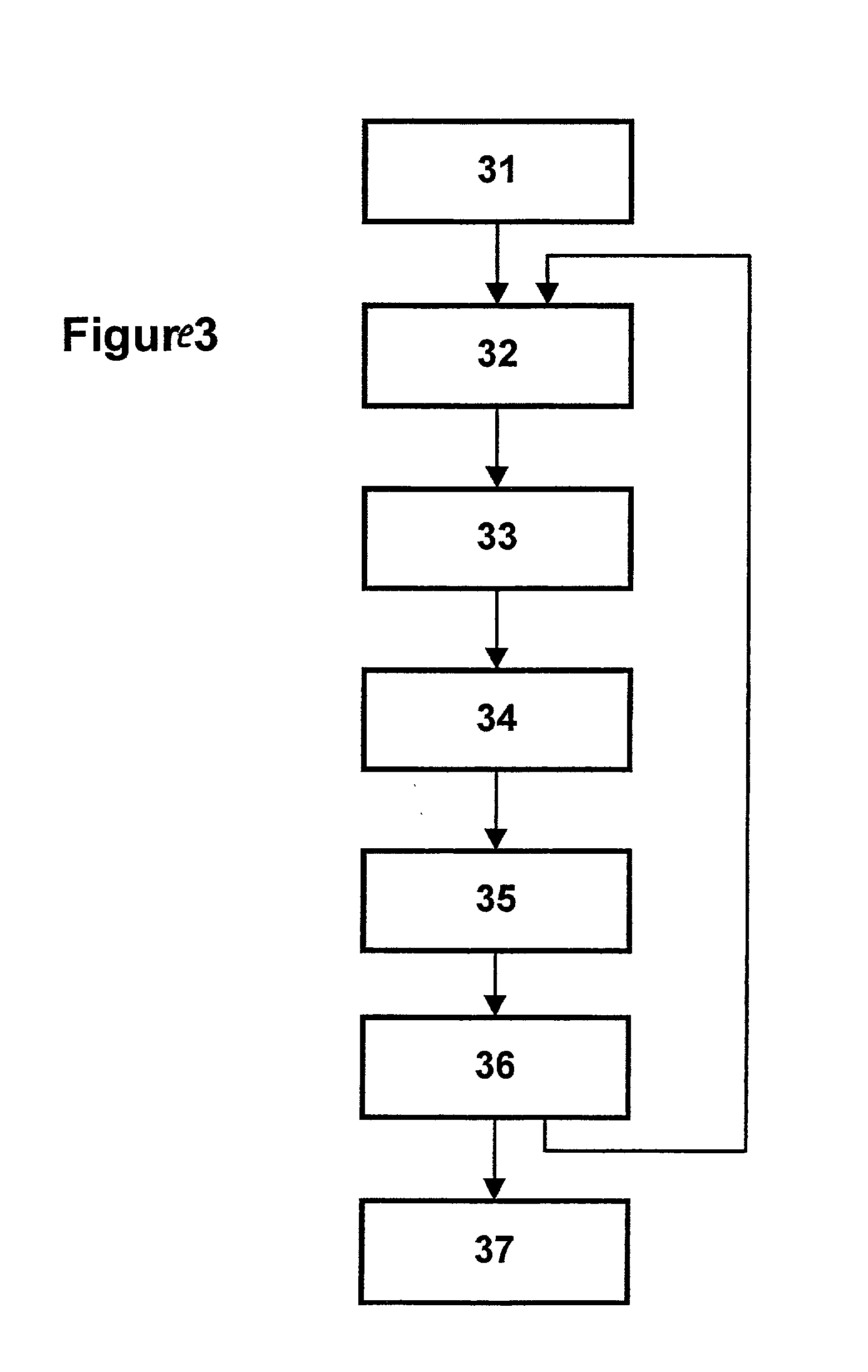
[0014] FIG. 3 shows a flow chart of the method according to the present invention; and

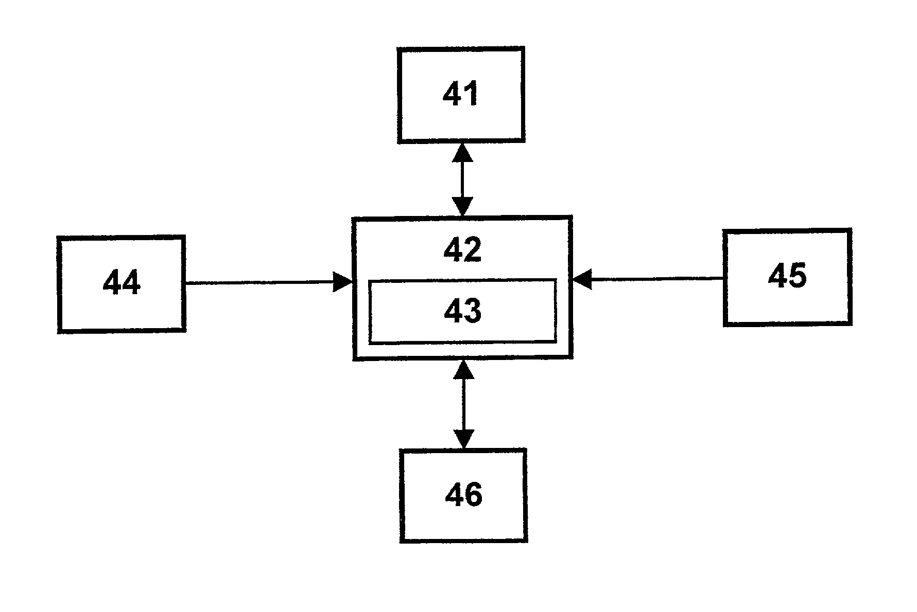
[0015] FIG. 4 shows a representation of a device according to the present invention.

[0016] FIG. 1 shows a motor vehicle 10, which is equipped with a motor vehicle radar system 11 according to the present invention, which, in this exemplary embodiment, is mounted in the travel direction, in the center of motor vehicle 10. Reference numeral 12 designates the longitudinal axis of the motor vehicle to which the beam direction of radar ...


PUM


Abstract

A method for detecting misalignment in a motor vehicle sensor system, in which signals are emitted, signals reflected by a stationary object are received, and a relative angle and a relative distance or a longitudinal displacement and a transverse displacement between the detected object and a reference axis of the motor vehicle as well as a relative velocity between the detected object and the motor vehicle are determined on the basis of the signals emitted and received, a correction value being determined for the relative angle on the basis of the relative angle, the relative distance, and a velocity of the vehicle in question or on the basis of the longitudinal displacement, the transverse displacement, and the vehicle's own velocity.

Description

[0001] The present invention relates to a method and device for detecting misalignment in a motor vehicle radar system or a motor vehicle sensor system according to the definition of the species in the independent claims. Such methods and such devices are used, for example, within the framework of an automatic cruise control system of a vehicle for detecting preceding vehicles. A system of this type is also known as Adaptive Cruise Control (ACC). When installing the motor vehicle radar system in the motor vehicle, an exact procedure and a precise alignment of a central axis of the radiated electromagnetic waves to a central line of the motor vehicle in the longitudinal direction are necessary.BACKGROUND INFORMATION[0002] U.S. Pat. No. 5,930,739 describes a method for measuring the yaw rate of a motor vehicle equipped with a LIDAR radar. In this method, the yaw rate ascertained by a yaw-rate sensor on the basis of the vehicle's own velocity, a longitudinal distance to a fixed detecti...

Claims


Application Information

Patent Timeline
IPC IPC(8): B60R21/00G01S7/40G01S7/497G01S7/52G01S13/91G01S13/931G01S15/931G01S17/931G08G1/16
CPCG01S7/4026G01S7/4972G01S7/52004G01S13/931G01S15/931G01S2013/9339G01S2007/403G01S2013/9353G01S2013/9364G01S2013/9367G01S2007/4091G01S17/936B60T7/22B60T17/221B60T8/17551B60T2250/062G01S2013/9323G01S2013/9329G01S2013/9324G01S2013/932G01S17/931G01S7/403G01S7/4091B60T2250/03
Inventor MICHI, HARALDLICHTENBERG, BERNDUHLER, WERNER
Owner ROBERT BOSCH GMBH
Learn More