Proportional needle control injector

a technology of proportional needle and injector, which is applied in the direction of liquid fuel feeder, valve operating means/releasing devices, machines/engines, etc., can solve the problems of fuel that is spilled either returning to the fuel supply or being wasted

Inactive Publication Date: 2002-11-14
CUMMINS INC
View PDF0 Cites 24 Cited by
  • Summary
  • Abstract
  • Description
  • Claims
  • Application Information

AI Technical Summary

Problems solved by technology

The use of a hydraulic amplifier requires that some fuel must be wasted to control the amplification.
Hydraulic amplifier's also allow undesirable oscillations of the controlled motion parts
The fuel that is spilled either returns to the fuel supply or is wasted.
A spill valve circuit needle control syst...

Method used


Image

  • Proportional needle control injector
  • Proportional needle control injector
  • Proportional needle control injector

Examples


Embodiment Construction

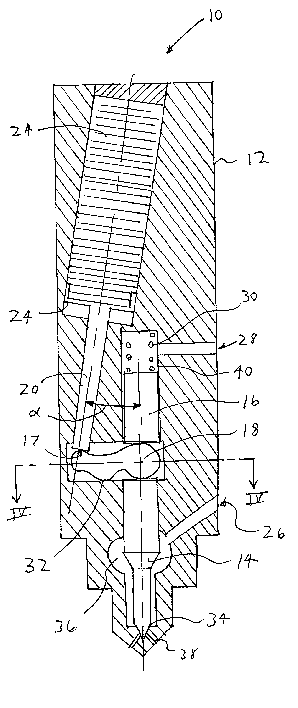
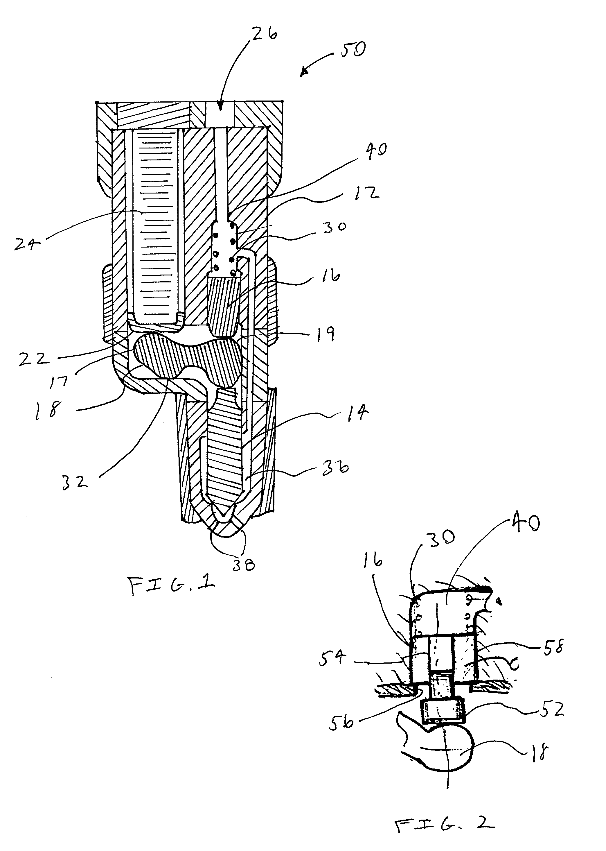
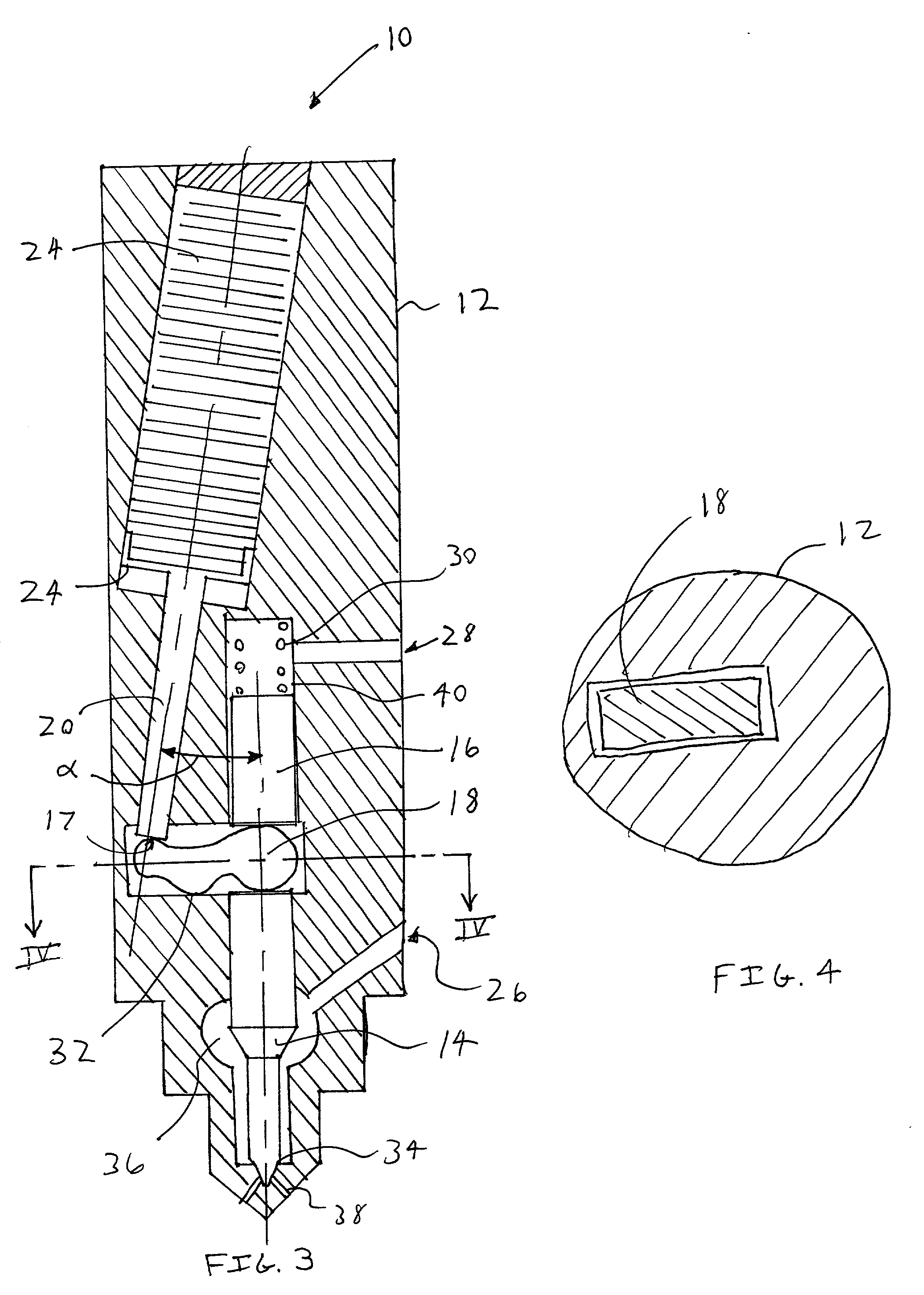
[0047] FIG. 1 shows a first exemplary embodiment of the fuel injector 50 in accordance with the invention. The fuel injector 50 includes an injector body 12, which houses a needle valve 14, a control piston 16, an actuator amplifying lever 18, an actuator guide 22, a solid state actuator 24 and a control piston spring 30. The injector body 12 also includes a common injection fuel inlet port 26 that communicates with both a nozzle needle chamber 36 and a control chamber 40. In this manner, the pressures in the nozzle needle chamber 36 that tend to lift the needle valve 14 are offset by the identical pressure in the control chamber 40 pushing downward upon the control piston 16.

[0048] The fuel injector 50 includes two separate controls. The first control for the fuel injector 10 is the solid state actuator 24. The solid state actuator 24 is connected to electrodes (not shown) and may be a piezoelectric, electro-strictive or magneto-strictive, but in the preferred embodiment the solid ...


PUM


Abstract

The fuel injector includes a solid state actuator that operates through an actuator motion amplifying lever to directly control the needle valve motion. Hydraulic forces, which act along the axes of the needle valve and the motion amplifying lever, are compensated by using a control piston, or other biasing means, to reduce the required amplitude of the control current/voltage and to reduce the required strength of the spring biasing the needle valve closed. The fuel injector may also include a control fuel inlet that is separate from the injection fuel inlet port.

Description

[0001] 1. Field of the Invention[0002] This invention relates generally to fluid injectors. More particularly, this invention relates to a proportional needle control fuel injector having a piezoelectric actuator and an actuator motion amplifying lever.[0003] 2. Description of Related Art[0004] Accurate control of fuel injection rate shape requires accurate control of the injector needle valve motion. Highly accurate electronic control of an injector needle valve motion may be provided by using solid state actuators such as piezoelectric, electro-strictive, or magneto-strictive actuators to control the needle valve position. To provide a desired valve displacement, conventional solid state actuators require high values of applied current and / or voltage.[0005] In an attempt to reduce the magnitude of the applied control current and / or voltage to the solid state actuators, and dimensions of the actuator, some fuel injectors include mechanical or hydraulic motion amplifiers. The use of...

Claims


Application Information

Patent Timeline
IPC IPC(8): F02M51/06F02M61/16F02M63/00
CPCF02M51/0603F02M2200/702F02M61/167
Inventor KIRZHNER, JOSEPHPETERS, LESTERCROFTS, JOHN D.ECKERLE, WAYNE
Owner CUMMINS INC
Why Eureka
Try Eureka