Passive safety system

a safety system and passive technology, applied in the direction of pedestrian/occupant safety arrangement, instruments, tractors, etc., can solve the problem of difficult calculation of precise integrated value, and achieve the effect of preventing the integral of acceleration and shortening the reset time of integrated acceleration valu

Inactive Publication Date: 2002-11-14
MITSUBISHI ELECTRIC CORP
View PDF0 Cites 12 Cited by
  • Summary
  • Abstract
  • Description
  • Claims
  • Application Information

AI Technical Summary

Benefits of technology

0016] The passive safety control means may have a high-frequency attenuation means attenuating a high-frequency with respect to an impact signal inputted from the acceleration sensor, the impact signal being a physical quantity operated on the basis of the impact acceleration detection signal inputted from the acceleration sensor, the high-frequency attenuation means including a high-frequency breaking circuit and a sectional balancing process means; and a feature of processing an operational result passed through the high-frequency attenuation means as an input value. In this way, it is possible to determine whether a collision necessitates an operation of the passive safety device or not, with stability without respect to a high-frequency noise.
0017] The passive safety control means may include a filter means extracting a frequency component being a physical quantity operated on the basis of the impact acceleration detection signal inputted from the acceleration sensor, which is peculiar to a collision of the vehicle from the acceleration signal inputted from the acceleration sensor; and a feature of processing an operational result passed through the filter means as an input value. In this way, it is possible to distinguish a normal state with stability from a collision state.
0018] The passive safety control means of the passive safety system may have features of dividing a physical quantity operated on the basis of the impact acceleration detection signal inputted from the acceleration sensor into the negative and positive components, setting a required weighted scaling with respect to the negative and positive components, and processing a multiplication result due to the weighted scaling as an input value. In this way, it is possible to prevent integral of the acceleration with respect to a vibration wave caused on a driving of a rough road. Inversely, when the weights are performed to input a value resulting from multiplying an attenuation directional component by a required scaling, the integrated acceleration value becomes small with respect to the attenuation directional component caused at the time of collision. The weights of the attenuation directional component are therefore different from those of the acceleration directional component, and it is possible to result in the collision being rapidly distinguished from the driving over the rough road.
0019] The passive safety control means of the passive safety system has features of computing a physical quantity based on the impact acceleration detection signal inputted from the acceleration sensor, setting maximum and minimum reference values of the physical quantity in normal driving, performing a computation with respect to addition of a present acceleration inputted from the acceleration sensor to the physical quantity when the physical quantity crosses a range defined between the maximum and minimum reference values, setting a function of operating a subtraction value or an addition value with respect to the present integrated acceleration value when the physical quantity remains within the range defined between the maximum and minimum reference values, and performing a subtraction or an addition of the integrated acceleration value based on the function to modify a reset period of the integrated acceleration value. In this way, it is possible to shorten a reset time of the integrated acceleration value.
0020] The passive safety control means of the passive safety system computes a physical quantity based on the impact acceleration detection signal inputted from the acceleration sensor, and sets maximum and minimum reference values of the physical quantity in normal driving. The passive safety control means then performs a subtraction of an integrated acceleration value when the integrated acceleration value at the time the physical quantity crosses a range defined between the maximum and minimum reference values is positive. Alternatively, the passive safety control means performs an addition of the integrated acceleration value when the integrated acceleration value at the time the physical quantity remains within the range defined between the maximum and minimum reference value is negative. It is therefore possible to monitor the integrated acceleration value at the present time. When the integrated acceleration value is positive, a subtraction of required value can be performed. When the integrated acceleration value is negative, an addition of required value can be performed. In this way, it is possible to perform a reset process so as to converge the integrated acceleration value in normal driving to zero at all times, and prevent the accumulation due to a superimposing of the noise component. It is therefore possible to calculate precisely the integrated acceleration value using a simple method without dividing a calculation of the integrated acceleration value into an accelerated direction and a decelerated direction.
0021] The acceleration sensor may be set to detect the acceleration in a longitudinal direction of the vehicle. In this case, when any one of front and rear sides is defined as the positive component of the acceleration sensor, the other side is defined as the negative component of the acceleration sensor, the passive safety control means may have features of operating controllably the passive safety device arranged at a positive component side when the integrated acceleration value based on the acceleration detection signal inputted from the acceleration sensor exceeds a reference value of the integrated acceleration value set as the positive component, and operating controllably the passive safety device arranged at a negative component side when the integrated acceleration value based on the acceleration detection signal inputted from the acceleration sensor does not attain a reference value of the integrated acceleration value set as the negative component. In this way, it is possible to determine a collision in both of front and rear collisions due to the same logic, and operate controllably the passive safety device without any error.

Problems solved by technology

In this case, since it is however difficult to reset in good timing, a reset process means for resetting the integrated value in good timing must be newly added to the existing constitution.
Since a ratio subtracted when a low-impact is inputted over a long time is however different from a ratio when a high-impact is inputted over a short time, it is difficult to calculate a precise integrated value.

Method used


Image

  • Passive safety system
  • Passive safety system
  • Passive safety system

Examples


embodiment 1

[0042] Embodiment 1

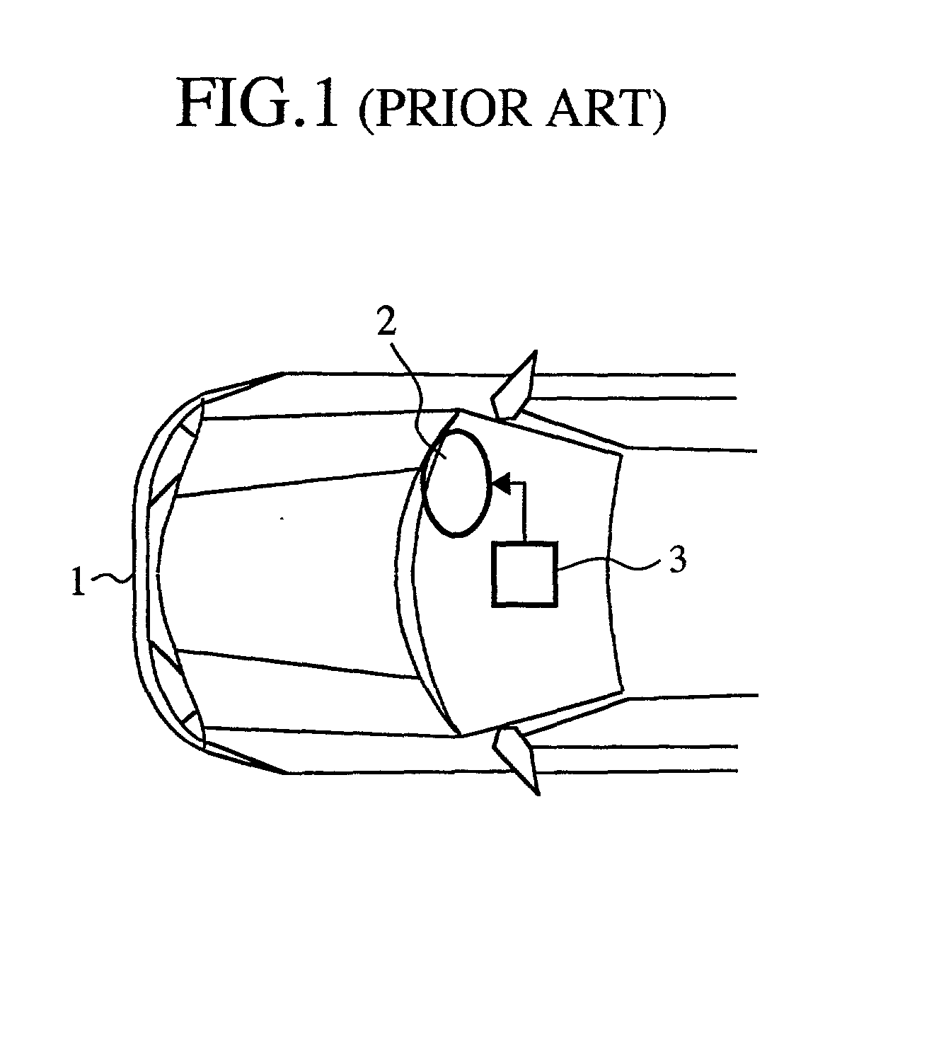
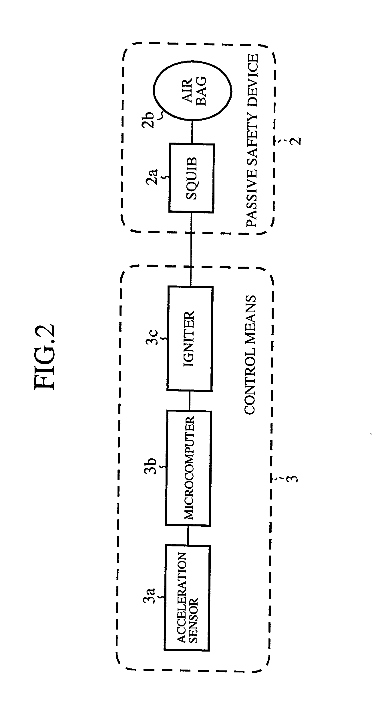
[0043] FIG. 2 is a general block diagram showing a passive safety system as embodiment 1 according to the present invention. Components of the embodiment 1 common to the conventional components shown in FIG. 1 are denoted by the same reference numerals and further description will be omitted.

[0044] In FIG. 2, a reference numeral 2 denotes a passive safety device mounted on the vehicle 1 (see FIG. 1). The passive safety device 2 includes a squib (initiation device) 2a and an airbag 2b expanded by the squib 2a. A reference numeral 3 denotes a control means controlling the passive safety device 2. The control means 2 includes an acceleration sensor 3a for detecting impact acceleration caused at the time of front-collision of the vehicle 1, a microcomputer 3b inputted the acceleration detection signal from the acceleration sensor 3a as a digital data due to an A / D converter, and an igniter 3c receiving an output signal from the microcomputer 3b to supply an ignition c...

embodiment 2

[0068] Embodiment 2

[0069] FIG. 7 is a plane view showing a front section of a vehicle providing with a passive safety system as embodiment 2 according to the present invention, and FIG. 8 is a block diagram showing the passive safety system of FIG. 7. Components of the embodiment 2 common to the components shown in FIG. 1 and FIG. 2 are denoted by the same reference numerals and further description will be omitted.

[0070] In FIG. 7, a reference numeral 1 denotes a vehicle, and a reference numeral 2 denotes a passive safety device for front-collision mounted on the vehicle 1. A reference numeral 4 denotes a passive safety device for rear-collision mounted on the vehicle 1. A reference numeral 3 denotes a common control means for driving both of the passive safety devices 3 and 4. As shown in FIG. 8, the control means 3 includes an acceleration sensor 3a for detecting impact acceleration caused at the time of front-collision of the vehicle 1, a microcomputer 3b inputted the acceleratio...

embodiment 3

[0084] Embodiment 3

[0085] FIG. 11 is a plane view showing a front section of a vehicle providing with a passive safety system as embodiment 3 according to the present invention, and FIG. 12 is a block diagram showing the passive safety system of FIG. 11. Components of the embodiment 3 common to the components shown in FIG. 2 to FIG. 10 and FIG. 1 are denoted by the same reference numerals and further description will be omitted.

[0086] In FIG. 11, a reference numeral 5 denotes a right-collision passive safety device mounted on the vehicle 1, and similarly a reference numeral 6 denotes a left-collision passive safety device mounted on the vehicle 1.

[0087] In FIG. 12, a reference numeral 3f denotes a right-collision igniter, and a reference numeral 3g denotes a left-collision igniter. These igniters 3f and 3g receive output signals from the microcomputer 3b to drive the right-collision passive safety device 5 and the left-collision passive safety device 6, respectively. Here, side-coll...


PUM


Abstract

A passive safety system has a passive safety device mounted on a vehicle, and a passive safety control means having an acceleration sensor detecting acceleration caused by an impact at the time of collision. The passive safety control means receives input an impact acceleration detection signal from the acceleration sensor and operates controllably the passive safety device. Further, the passive safety control means computes a physical quantity based on the impact acceleration detection signal inputted from the acceleration sensor, sets maximum and minimum reference values of the physical quantity in normal driving, performs a computation with respect to addition of a present acceleration inputted from the acceleration sensor to an integrated acceleration value at this point in time when the physical quantity crosses a range defined between the maximum and minimum reference values, and performs a computation with respect to a reset process of the integrated acceleration value when the physical quantity remains within the range defined between the maximum and minimum reference values.

Description

[0001] 1. Field of the Invention[0002] The present invention relates to a passive safety system including a passive safety device and a control device operating controllably the passive safety device. Especially, the present invention relates to a passive safety system having features of determining whether impacts at the time of collision necessitate an operation of the passive safety device or not, and controlling the operation of the passive safety device based on the determined result.[0003] 2. Description of the Prior Art[0004] FIG. 1 is a plan view showing a front section of a vehicle (automobile) including a conventional passive safety system. In the drawing, a reference numeral 1 denotes a vehicle, 2 denotes an airbag acting as a passive safety device arranged at a front of seats mounted on the vehicle 1, and 3 denotes a passive safety control means developing the airbag 2. The passive safety control means 3 includes an acceleration sensor (not shown) and a microcomputer (no...

Claims


Application Information

Patent Timeline
Patent Type & Authority Applications(United States)
IPC IPC(8): B60R21/16B60R21/01B60R21/013B60R21/015
CPCB60R21/0132B60R21/0156B60R2021/01304B60R2021/01302B60R21/0133B60R21/01336B60R21/01B60R2021/01322
Inventor YAMASHITA, TOSHIYUKI
Owner MITSUBISHI ELECTRIC CORP
Why Eureka
Try Eureka