USB connection-detection circuitry and operation methods of the same

a technology of usb connection and operation method, applied in the direction of instruments, computing, electric digital data processing, etc., can solve the problem of forbidden data transmission directly from one usb function device to another usb function devi

Inactive Publication Date: 2002-11-14
PROLIFIC TECH INC
View PDF4 Cites 133 Cited by
  • Summary
  • Abstract
  • Description
  • Claims
  • Application Information

AI Technical Summary

Benefits of technology

[0016] Therefore, one object of the invention is to provide a circuitry, which enables a USB device to connect to a USB device or a USB host arbitrarily.
[0017] Further, another object of the invention is to provide an operation method of the circuitry such that a USB device containing such circuitry is able to identify the device type of a USB device or a USB host to which it is connected.

Problems solved by technology

A drawback of the connection-detection circuitry mentioned above is that it is designed with USB standard specifications, that is, the devices which are connected to each other through the connection-detection circuitry must maintain a host-device relationship in order to fulfill the tiered star topology of a USB bus.
Thus, under such circumstances, a USB function device only can be connected to a USB hub device or a USB host device and cannot be connected to another USB function device.
As a result, the data transmission directly from one USB function device to another USB function device is forbidden.

Method used


Image

  • USB connection-detection circuitry and operation methods of the same
  • USB connection-detection circuitry and operation methods of the same
  • USB connection-detection circuitry and operation methods of the same

Examples


first embodiment

[0026] Refer to FIG. 3, a connection-detection circuitry of the first embodiment according to the present invention is shown in the figure. The Connection-detection circuitry 500 includes a pair of differential signal lines 503, 504, a pair of pull-down resistor 506, 507, a pair of pull-up resistor 508, 509, a power supply system 510, and a set of manual switching elements 511. Wherein, the differential signal line 503 is used to connect to a D+ differential signal Line 403 of a USB cable 40 while the differential signal line 504 is used to connect to a D- differential signal line 404 of the USB cable 40. The connection-detection circuitry 500 of this embodiment is a manual-switch mode circuitry.

[0027] If a USB "Devicehost" device 50 containing such connection-detection circuitry 500 is to be connected to a USB host or a USB hub device, the user can use a set of manual-switch elements 511 to set the USB Devicehost device 50 into "Device-Mode" before the connection. Under Device-Mode...

second embodiment

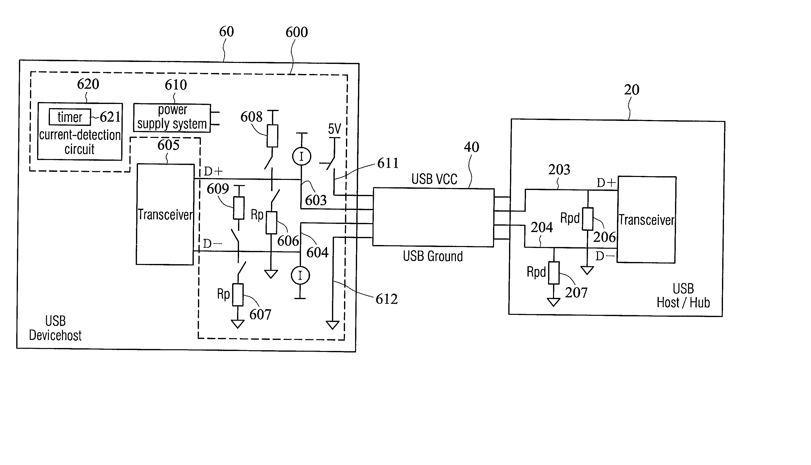
[0032] With reference to FIG. 4a and 4b, a connection-detection circuitry 600 of the second embodiment according to the invention is shown in the figures. The connection-detection circuitry 600 includes a pair of differential signal lines 603, 604, a power line 611, a ground line 612, a pair of pull-down resistors 606, 607, a pair of pull-up resistors 608, 609, a power supply system 610, and a current-detection circuit 620. Wherein, the differential signal lines 603, 604 are used to connect to the D+ and D- differential signal line 403, 404 of the USB cable 40 ; while each of the pull-down resistors 606 and the pull-up resistor 608 is connected to the differential signal line 603 with a switching element, and each of the pull-down resistor 607 and the pull-up resistor 609 is connected to the differential line 604 with a switching element, separately. Further, a timer 621 is constructed in the current-detection circuit 620 and will be explained in details later. Besides, the power su...

third embodiment

[0042] Refer to FIG. 5a and 5b, a connection-detection circuitry 700 of the third embodiment according to the invention is shown in the figures. The connection-detection circuitry 700 of Voltage-Detection Mode includes a pair of differential signal lines 703, 704, a power line 711, a ground line 712, a pair of pull-down resistors 706 and 707, a pair of pull-up resistors 708 and 709, a pair of up-stream resistors 701 and 702, a power supply system 710, and a voltage-detection circuit 720. Wherein, the differential signal lines 703 and 704 are used to connect to the D+ and D- differential signal lines 403 and 404 of the USB cable 40, respectively. Each of the pull-down resistor 706, the pull-up resistor 708 and the up-stream resistor 701 is connected to the differential signal line 703 with a switching element, individually. Meanwhile, each of the pull-down resistor 707, the pull-up resistor 709, and the up-stream resistor 702 is connected to the differential signal line 704 with a sw...


PUM


Abstract

A USB connection-detection circuitry and the operation method of the same are disclosed. The circuitry includes a transmitting circuit and a detecting circuit. The transmitting circuit contains a pair of differential signal lines, a pair of pull-down resistors and a pair of pull-up resistors wherein one pull-down resistor and one pull-up resistor are connected to the same differential signal line with their own individual switches. A power-related signal supplied by a power-supply system is received by the transmitting circuitry and transmitted through a differential signal line. Then, the power-related signal is grounded via a pull-down resistor. The detecting circuit is utilized to detect the power-related signals, which flow through the differential lines. When a device is connected to this connection-detection circuitry with a USB cable, the differential signal lines of the USB cable are connected with the differential signal lines of this circuitry. This results in the variation of the power-related signals, which are connected to the ground through the pull-down resistors originally. Therefore, by comparing the difference of the power-related signals before and after the connection, the connection-detection circuitry is able to automatically identify the mode of the device, which connects to the circuitry.

Description

[0001] This invention relates generally to a circuitry and its operating methods, more particularly to a Connection-detection circuitry and its operating methods used in a USB system.DESCRIPTION OF THE RELATED ART[0002] Universal Serial Bus (USB) is a new interface proposed by several major computer manufactures to solve the inextricable problems experienced when installing and extending a conventional computer system and its peripheral equipments. Under this system, all peripherals can communicate with the host computer through the same interface, i.e., a USB bus. Moreover, one of its distinguishing features is that all USB peripherals are provided with "plug and play" function. That is to say, it is no longer a necessity to switch off the host computer or to install the drivers prior the installation or removing of such devices.[0003] In accordance with the USB specification, each USB system is consist of three elements: a USB host, a USB inter-connection interface, and a USB devi...

Claims


Application Information

Patent Timeline
Patent Type & Authority Applications(United States)
IPC IPC(8): G06F3/00G06F13/14G06F13/40H04L12/44H04L29/10
CPCG06F13/4081
Inventor WU, WEN-JEN
Owner PROLIFIC TECH INC
Why Eureka
Try Eureka