
Transmission lines for CMOS integrated circuits

a technology of integrated circuits and transmission lines, applied in semiconductor devices, semiconductor/solid-state device details, instruments, etc., can solve problems such as difficult solutions, and achieve the effects of reducing signal delay, and reducing skew and crosstalk

Inactive Publication Date: 2009-06-30
MICRON TECH INC
View PDF223 Cites 15 Cited by
  • Summary
  • Abstract
  • Description
  • Claims
  • Application Information

AI Technical Summary

Benefits of technology

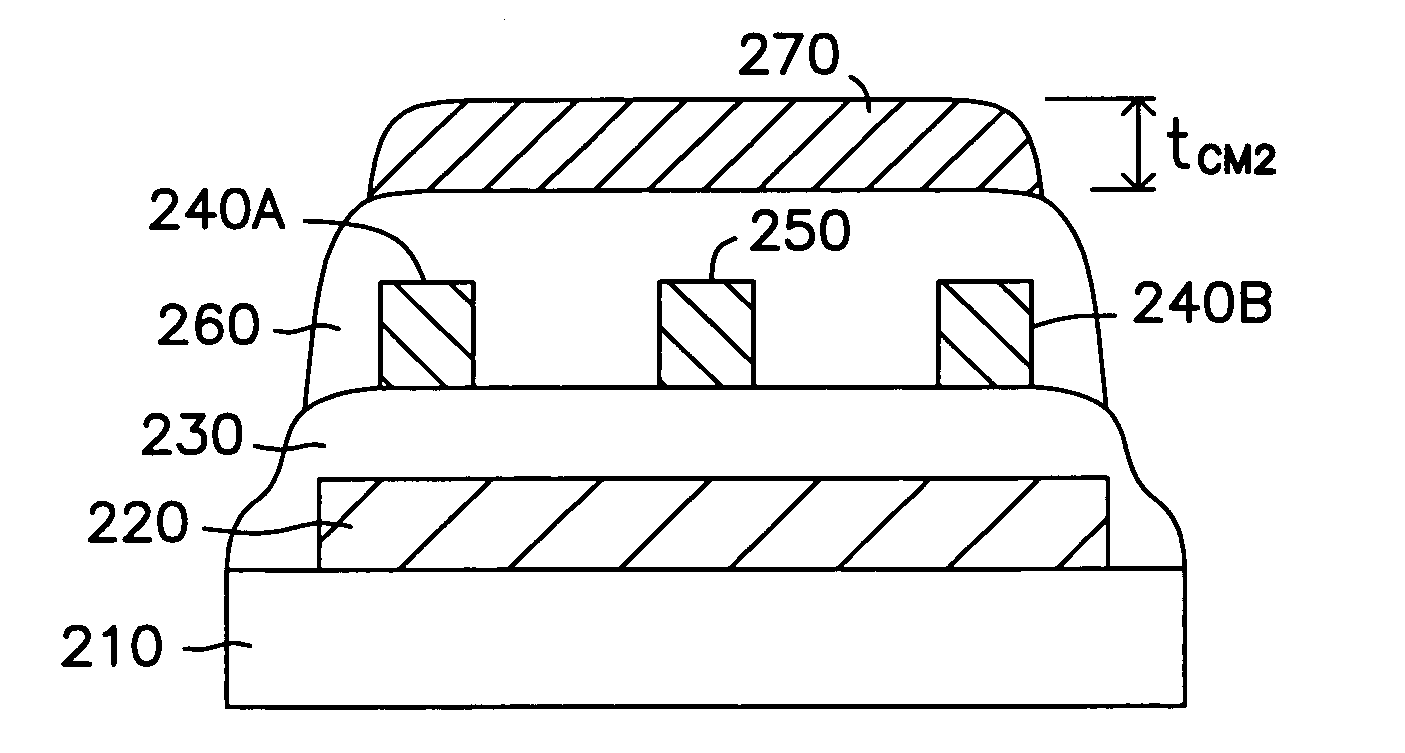
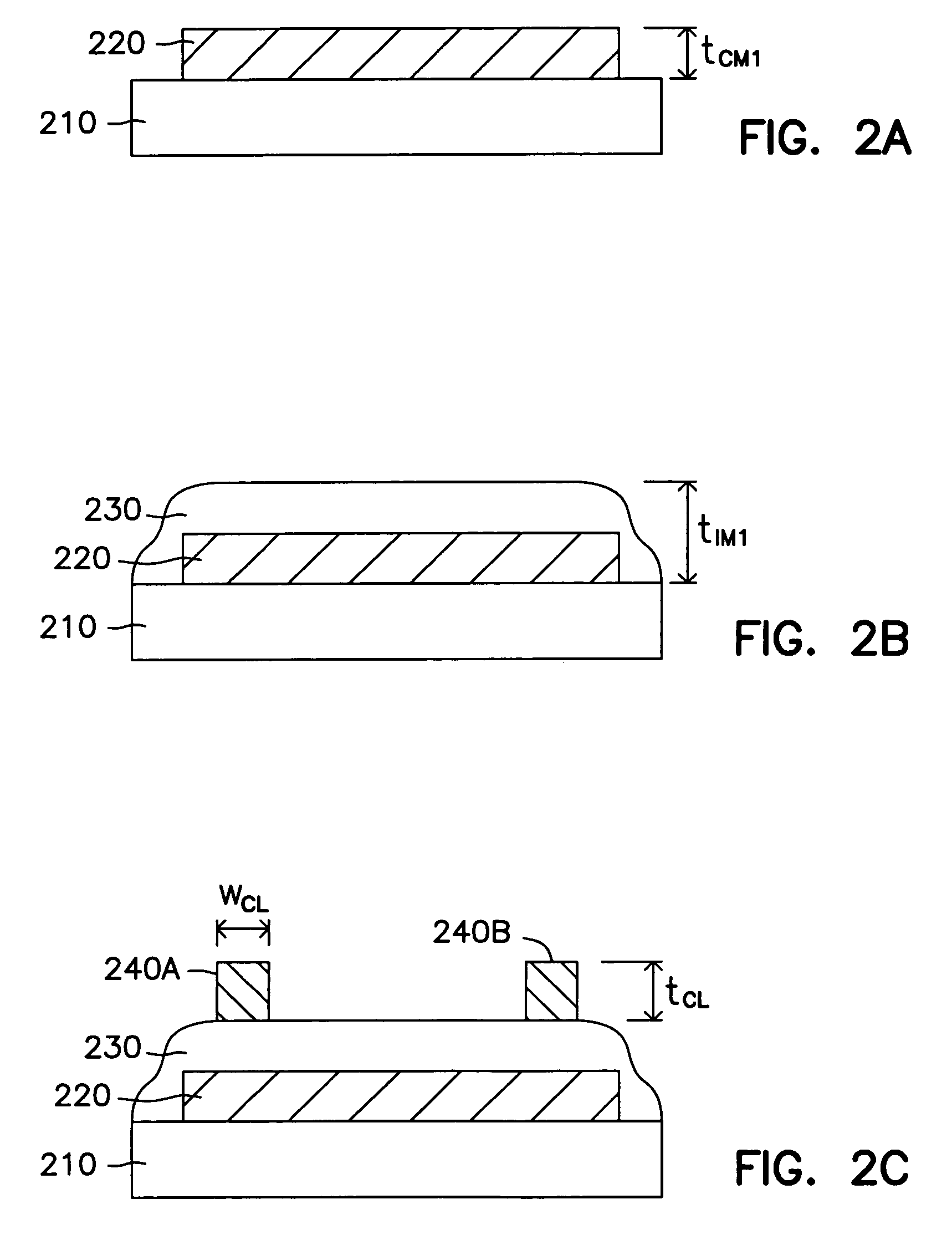
[0006]Improved methods and structures are provided for impedance-controlled low-loss transmission lines in CMOS integrated circuits. The present invention offers a reduction in signal delay. Moreover, the present invention further provides a reduction in skew and crosstalk. Embodiments of the present invention also provide the fabrication of improved transmission lines for silicon-based integrated circuits using conventional CMOS fabrication techniques.

Problems solved by technology

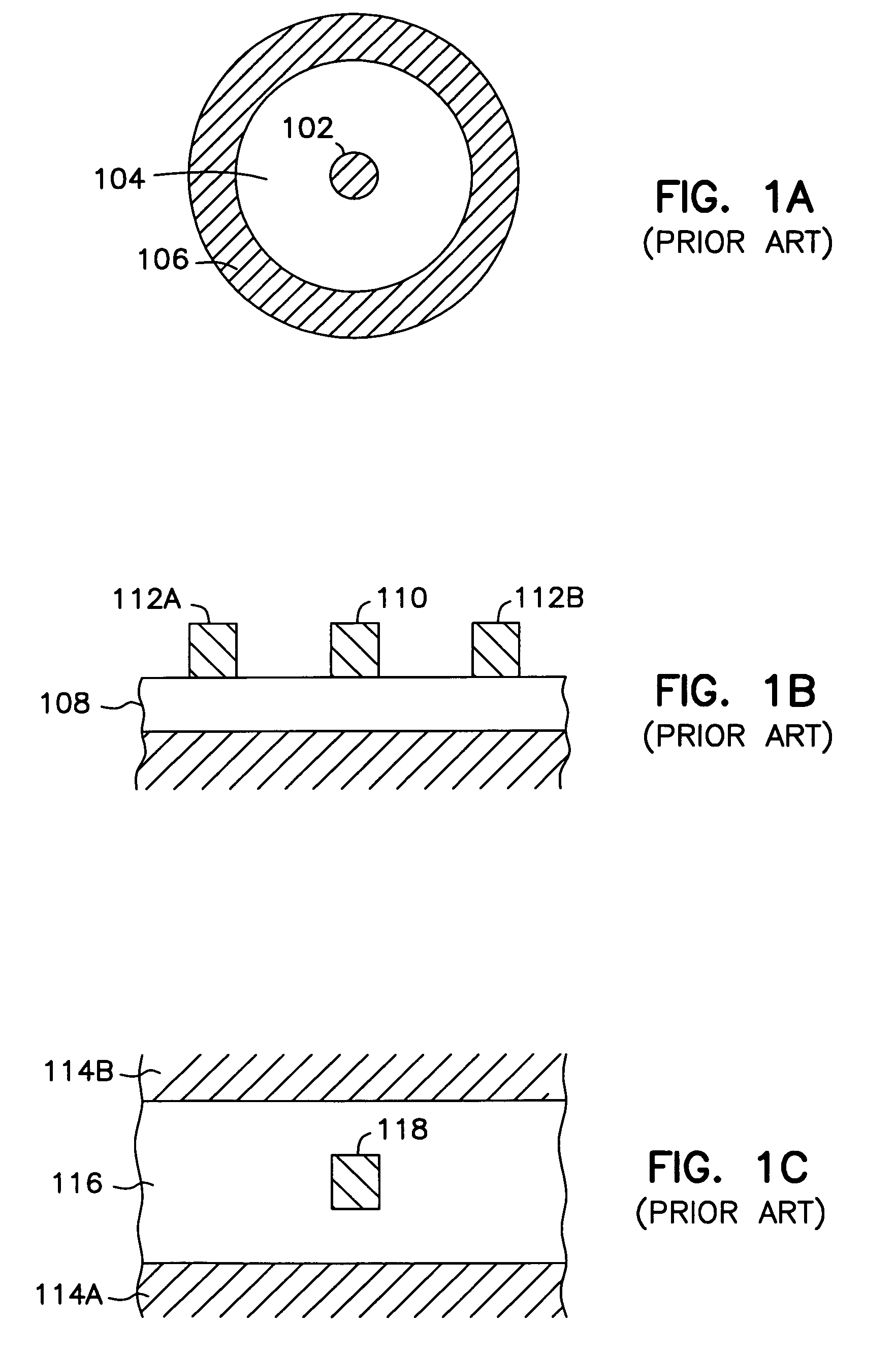
Additionally, because power supply ringing and substrate bounce are becoming so problematic, metal power supply and ground planes have been incorporated into these types of circuits. FIG. 1B illustrates the incorporation of these power supply and ground planes.
Due to the continued reduction in scaling and increases in frequency for transmission lines in integrated circuits such solutions remain a difficult hurdle.

Method used


Image

  • Transmission lines for CMOS integrated circuits
  • Transmission lines for CMOS integrated circuits
  • Transmission lines for CMOS integrated circuits

Examples


Embodiment Construction

[0021]In the following detailed description of the invention, reference is made to the accompanying drawings which form a part hereof, and in which is shown, by way of illustration, specific embodiments in which the invention may be practiced. In the drawings, like numerals describe substantially similar components throughout the several views. These embodiments are described in sufficient detail to enable those skilled in the art to practice the invention. Other embodiments may be utilized and structural, logical, and electrical changes may be made without departing from the scope of the present invention.

[0022]The terms wafer and substrate used in the following description include any structure having an exposed surface with which to form the integrated circuit (IC) structure of the invention. The term substrate is understood to include semiconductor wafers. The term substrate is also used to refer to semiconductor structures during processing, and may include other layers that ha...


PUM


Abstract

Improved methods and structures are provided for impedance-controlled low-loss lines in CMOS integrated circuits. The present invention offers a reduction in signal delay. Moreover, the present invention further provides a reduction in skew and crosstalk. Embodiments of the present invention also provide the fabrication of improved transmission lines for silicon-based integrated circuits using conventional CMOS fabrication techniques. One method of the present invention provides transmission lines in an integrated circuit. Another method includes forming transmission lines in a memory device. The present invention includes a transmission line circuit, a differential line circuit, a twisted pair circuit as well as systems incorporating these different circuits all formed according to the methods provided in this application.

Description

[0001]This application is a Continuation of U.S. application Ser. No. 10 / 164,475 filed Jun. 6, 2002 now U.S. Pat. No. 7,101,778 which is a Divisional of U.S. application Ser. No. 09 / 364,199, filed Jul. 30, 1999, now U.S. Pat. No. 6,373,740, which are incorporated herein by reference.FIELD OF THE INVENTION[0002]The present invention relates to integrated circuit devices, and more particularly, to a method and structure for providing novel transmission lines for CMOS integrated circuits.BACKGROUND OF THE INVENTION[0003]As clocking systems and switching speeds on integrated circuits progress into the GigaHertz (GHz) range and beyond, chip interconnects become more and more critical. Signal delays on transmission lines terminated in their characteristic impedance are of the order of 70 picoseconds per centimeter (ps / cm) when oxide insulators are used. Long signal connections and clock distribution lines operating in the GHz range require the use of low impedance terminated transmission ...

Claims


Application Information

Patent Timeline
Patent Type & Authority Patents(United States)
IPC IPC(8): G11C5/02
CPCH01L23/5225H01L2924/3011H01L2223/6627H01L2924/0002H01L2924/00
Inventor FORBES, LEONARDCLOUD, EUGENE H.AHN, KIE Y.
Owner MICRON TECH INC
Learn More