Differential line driver circuit and method therefor

a driver circuit and differential line technology, applied in the field ofdifferential line driver circuits, can solve the problems of significant disturbance of closed-loop feedback circuits, significant delay, impedance matching and design difficulty,

Active Publication Date: 2015-05-28
NXP USA INC
View PDF6 Cites 16 Cited by
  • Summary
  • Abstract
  • Description
  • Claims
  • Application Information

AI Technical Summary

Problems solved by technology

However, such closed-loop feedback circuits are significantly disturbed during EME (or electromagnetic interference (EMI)) events.
A further requirement of such differential line drivers used within automotive applications is to reduce differential ringing on the transmission lines, which is a direct result of non-optimal terminated network transmission lines.
When ringing is excessive, the receiver ...

Method used


Image

  • Differential line driver circuit and method therefor
  • Differential line driver circuit and method therefor
  • Differential line driver circuit and method therefor

Examples


Embodiment Construction

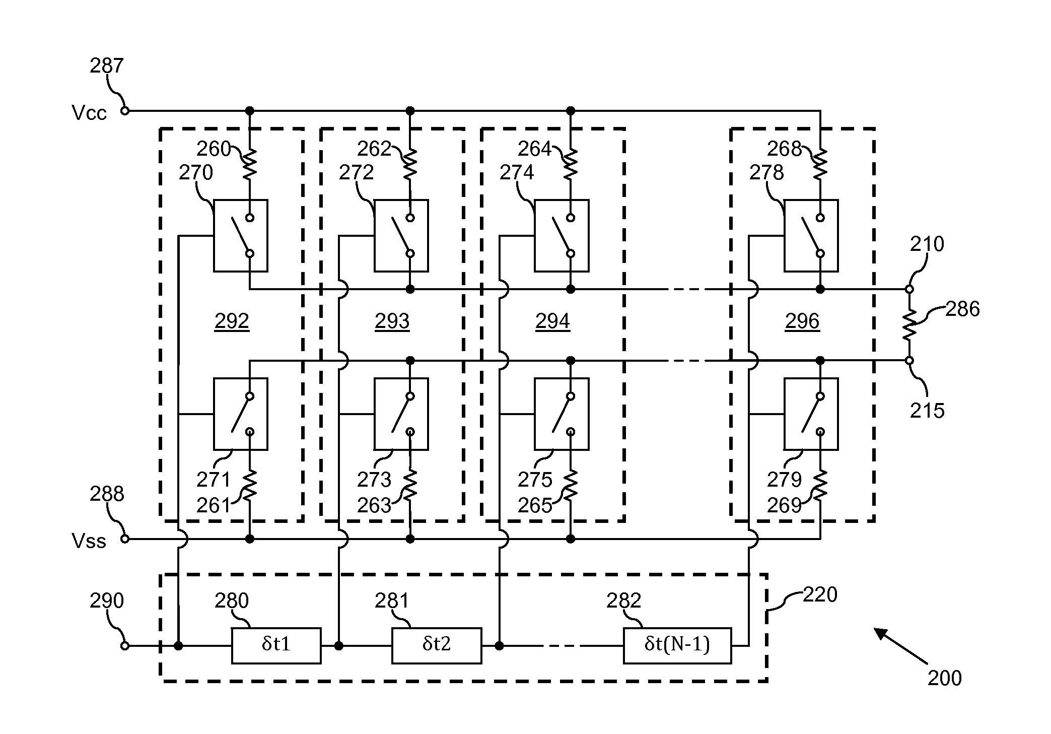
[0017]An example of an embodiment of a multi-stage line driver circuit will now be described with reference to a Controller Area Network (CAN) driver. However it will be apparent that the present invention is not limited to a CAN driver, and may equally be implemented within drivers for alternative network systems in which it is necessary or desirable to control the rise and fall of an output signal, for example to minimise ringing, etc.

[0018]Furthermore, because the illustrated embodiments of the present invention may for the most part, be implemented using electronic components and circuits known to those skilled in the art, details will not be explained in any greater extent than that considered necessary, as illustrated below, for the understanding and appreciation of the underlying concepts of the present invention and in order not to obfuscate or distract from the teachings of the present invention.

[0019]Referring first to FIG. 2, there is illustrated a simplified block diagra...


PUM


Abstract

A differential line driver circuit comprising a plurality of driver stages is described. Each driver stage is operably coupled to at least one output of the line driver circuit and arranged to receive at least one control signal and to drive at least one output signal on the at least one output of the line driver circuit in accordance with the at least one control signal received thereby. The line driver circuit further comprises at least one delay component arranged to receive the at least one control signal, and to sequentially propagate the at least one control signal to the driver stages with time delays between the propagation of the at least one control signal to sequentially adjacent driver stages. The delay component is arranged to sequentially propagate the at least one control signal to the driver stages such that such that the at least one control signal is propagated with at least one of: a progressively increasing time delay between sequentially adjacent driver stages; and a progressively decreasing time delay between sequentially adjacent driver stages.

Description

FIELD OF THE INVENTION[0001]The field of this invention relates to a differential line driver circuit and a method of driving an output signal for transmission over at least one communication line.BACKGROUND OF THE INVENTION[0002]Differential line drivers, such as those used within Controller Area Network (CAN) devices, typically drive unshielded twisted pair (UTP) transmission lines, which connect Electronic Control Units (ECUs) and the like to, for example, modules containing sensors or other ECUs. One requirement of such differential line drivers used within automotive applications is that they generate a low level of electromagnetic emission (EME).[0003]In order to achieve a differential signal driver capable of generating the required low EME, one needs to make the generated signals as differential as possible. In addition, one needs to minimize power supply noise, and in particular on chip digital power supply noise, which is coupled through the final switch's gate drain capac...

Claims


Application Information

Patent Timeline
IPC IPC(8): G06F13/40
CPCG06F13/4072
Inventor PARDOEN, MATTHIJS
Owner NXP USA INC
Why Eureka
Try Eureka