Wiring method of differential signal line and PCB

A technology of differential signal lines and wiring methods, applied in the directions of circuit substrate materials, printed circuits, electrical components, etc., can solve the problems of high cost, long wiring time, and occupying a lot of wiring space, and achieve the effect of strong practicability

Active Publication Date: 2016-06-22
ZTE CORP
View PDF3 Cites 16 Cited by
  • Summary
  • Abstract
  • Description
  • Claims
  • Application Information

AI Technical Summary

Problems solved by technology

[0009] The main technical problem to be solved by the present invention is to provide a wiring method for differential signal lines and a PCB board, which can sol

Method used


Image

  • Wiring method of differential signal line and PCB
  • Wiring method of differential signal line and PCB
  • Wiring method of differential signal line and PCB

Examples


Embodiment 1

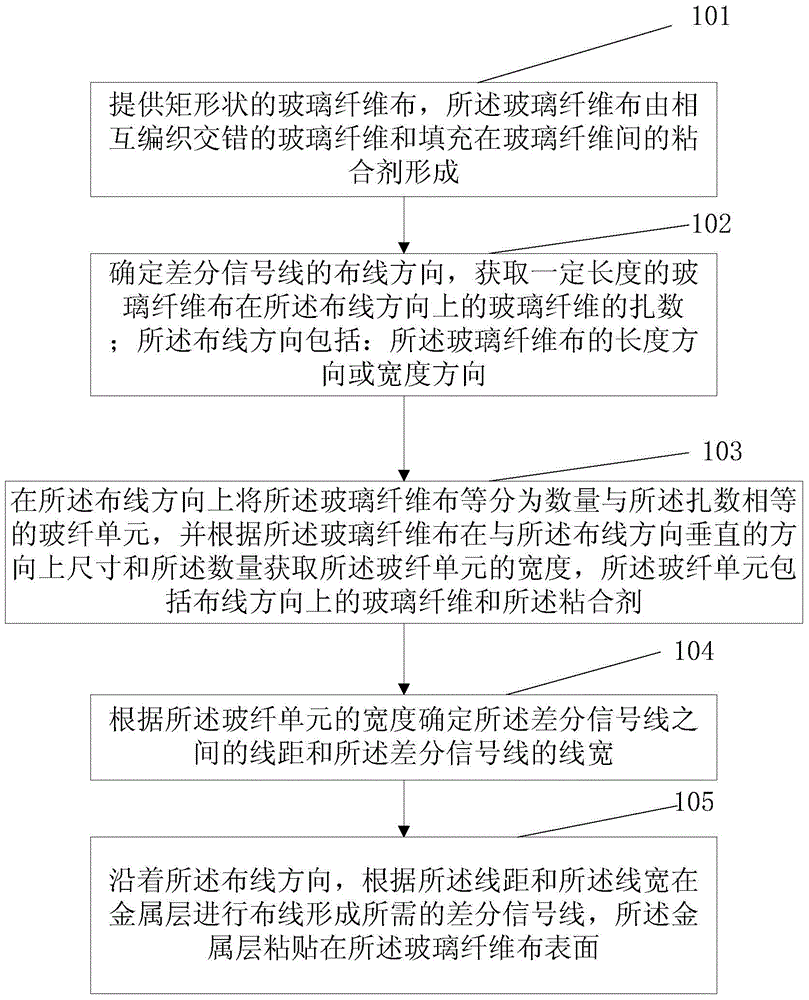
[0055] Considering the technical problems of high cost, large wiring space and long wiring time in the existing wiring method for controlling differential signal delay, this embodiment provides a wiring method for differential signal lines, such as figure 1 shown, including the following steps:

[0056] Step 101: Provide a rectangular glass fiber cloth, the glass fiber cloth is formed by weaving interlaced glass fibers and an adhesive filled between the glass fibers.

[0057] In this embodiment, the rectangular glass fiber cloth includes: interlaced glass fibers, the glass fibers in the length direction of the rectangular glass fiber cloth are called weft threads, and the glass fibers in the width direction are called warp threads.

[0058] Step 102: Determine the wiring direction of the differential signal line, and obtain the number of glass fiber bundles of the glass fiber cloth in the wiring direction; the wiring direction includes: the length direction or the width direct...

Embodiment 2

[0118] In this embodiment, the wiring method described in the first embodiment is introduced by wiring in the warp direction, which includes the following steps:

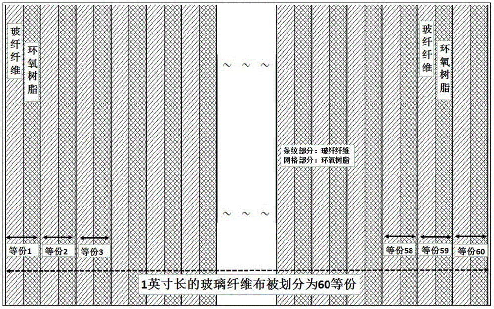
[0119] Step S01: First, according to the needs of high-speed signals and lamination, select the appropriate specification of glass fiber cloth, check the number of bundles according to the IPC standard, and obtain the number of bundles of warp and weft threads of this glass fiber specification as m×n, from which each Equivalent value X, meridian direction X=1000 / m(mil), refer to figure 2 ;

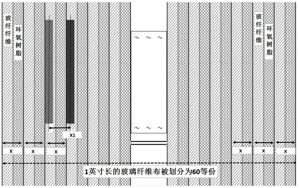
[0120] Step S02: According to the layout of the backplane, select the wiring direction that meets the requirements. If the warp direction is selected for wiring, then design the center distance of the differential line X1=X=1000 / m (mil), refer to image 3 ;

[0121] Step S03: According to the differential line center distance X1, under the premise of determining the differential impedance, follow the design method of using wi...

Embodiment 3

[0130] This embodiment provides a PCB board, comprising: a rectangular glass fiber cloth and a metal layer pasted on the surface of the glass fiber cloth by an adhesive; The adhesive between the glass fibers is formed; a differential signal line pair is formed on the metal layer, and the differential signal line pair extends along the dimension direction of the glass fiber cloth; direction, the glass fiber cloth includes a number of glass fiber units equal to the number of glass fiber strands, and the glass fiber unit includes: glass fibers in the dimension direction of the glass fibers and the binder

[0131] The line spacing between the differential signal lines and the line width of the differential signal lines are determined according to the width of the glass fiber unit;

[0132] The dimension direction of the glass fiber includes: the length or width direction of the glass fiber.

[0133] Preferably, the center-to-center distance between the differential signal line pa...


PUM


Abstract

The invention discloses a wiring method of a differential signal line and a PCB. The wiring method includes: rectangular fiberglass fabrics are provided, and the fiberglass fabrics are formed by fiberglass mutually woven in a staggered manner and adhesives filled between the fiberglass; the wiring direction of the differential line is determined, and the bundle number of the fiberglass of the fiberglass fabrics in the direction is obtained; the wiring direction comprises the length direction or the width direction of the fiberglass fabrics; the fiberglass fabrics are divided into fiberglass units with the number equal to the bundle number in the wiring direction, the width of the fiberglass units is obtained according to the dimension and the quantity of the fiberglass fabrics in the direction vertical to the wiring direction, and the fiberglass units comprise fiberglass in the wiring direction and the adhesives; the line distance and the line width of the differential signal line are determined according to the width of the fiberglass units; and wiring is performed on a metal layer along the wiring direction according to the line distance and the line width to form the required differential signal line, and the metal layer is pasted on the surface of the fiberglass fabrics. According to the method, the problems of high cost, large occupied wiring space, and long wiring time of the conventional control differential signal delay wiring method are solved.

Description

technical field [0001] The invention relates to the field of wiring design, in particular to a wiring method for differential signal lines and a PCB board. Background technique [0002] Under the background of increasing communication traffic and miniaturization of communication equipment, the signal rate of mainstream Serdes has been increased to 10.3125Gbps, 12.5Gbps, and even will be directly upgraded to 25Gbps in the next step; Quality, especially the control of skew between p / n, puts forward more stringent requirements. [0003] In addition to the difference in the physical size of the PCB wiring, the generation of the differential signal skew is caused by the glass fiber effect of the glass fiber cloth; because the formation of the glass fiber cloth is completed by bonding and laminating the glass fibers with epoxy resin. ; The difference in glass fiber height and epoxy resin content between the warp and weft of the glass fiber and the weaving interval leads to differ...

Claims


Application Information

Patent Timeline
IPC IPC(8): H05K3/00H05K3/10H05K1/05H05K1/02
CPCH05K1/0248H05K1/0366H05K2201/029H05K1/0245H05K3/10H05K1/0306
Inventor 郭涛马峰超张远望
Owner ZTE CORP
Why Eureka
Try Eureka