This helps you quickly interpret patents by identifying the three key elements:
Problems solved by technology
Method used
Benefits of technology
0173] FIG. 161 is a side elevation of an exemplary implementation of a safety stop in the context of a table saw.
0174] FIG. 162 is a side elevation of an exemplary implementation of a safety stop in the conte
Problems solved by technology
Unfortunately, the power and high operating speeds of mechanized equipment creates a risk for those operating such machinery.
Each year thousands of people are maimed or killed by accidents involving power equipment.
In many cases, guards are effective to reduce the risk of injury, however, there are many instances where the nature of the operations to be performed precludes using a guard that completely blocks access to hazardous machine parts.
These systems interrupt or reverse power to the motor or disengage a clutch upon contact with a user's hand by any dangerous portion of the machine.
Although such systems are suitable for use with meat skinning machines, they are relatively slow to stop the motion of the cutting element because they rely on the operation of solenoids or must overcome the inertia of the motor.
Unfortunately, such a system is prone to false triggers and is relatively slow acting because of the solenoid.
However, the syst
Method used
Image
Click on the blue label to locate the original text in one second.
Reading with bidirectional positioning of images and text.
Examples
Embodiment Construction
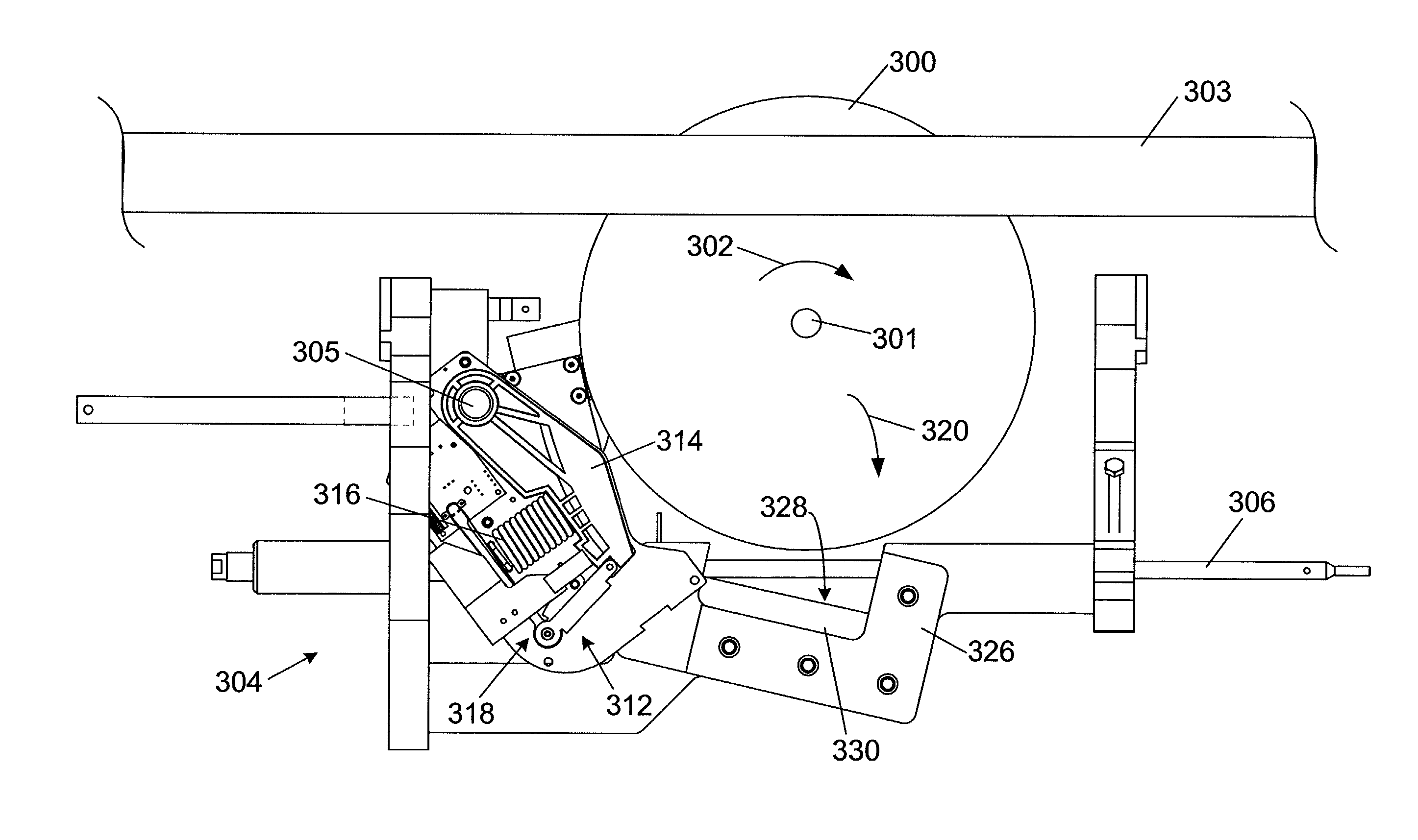
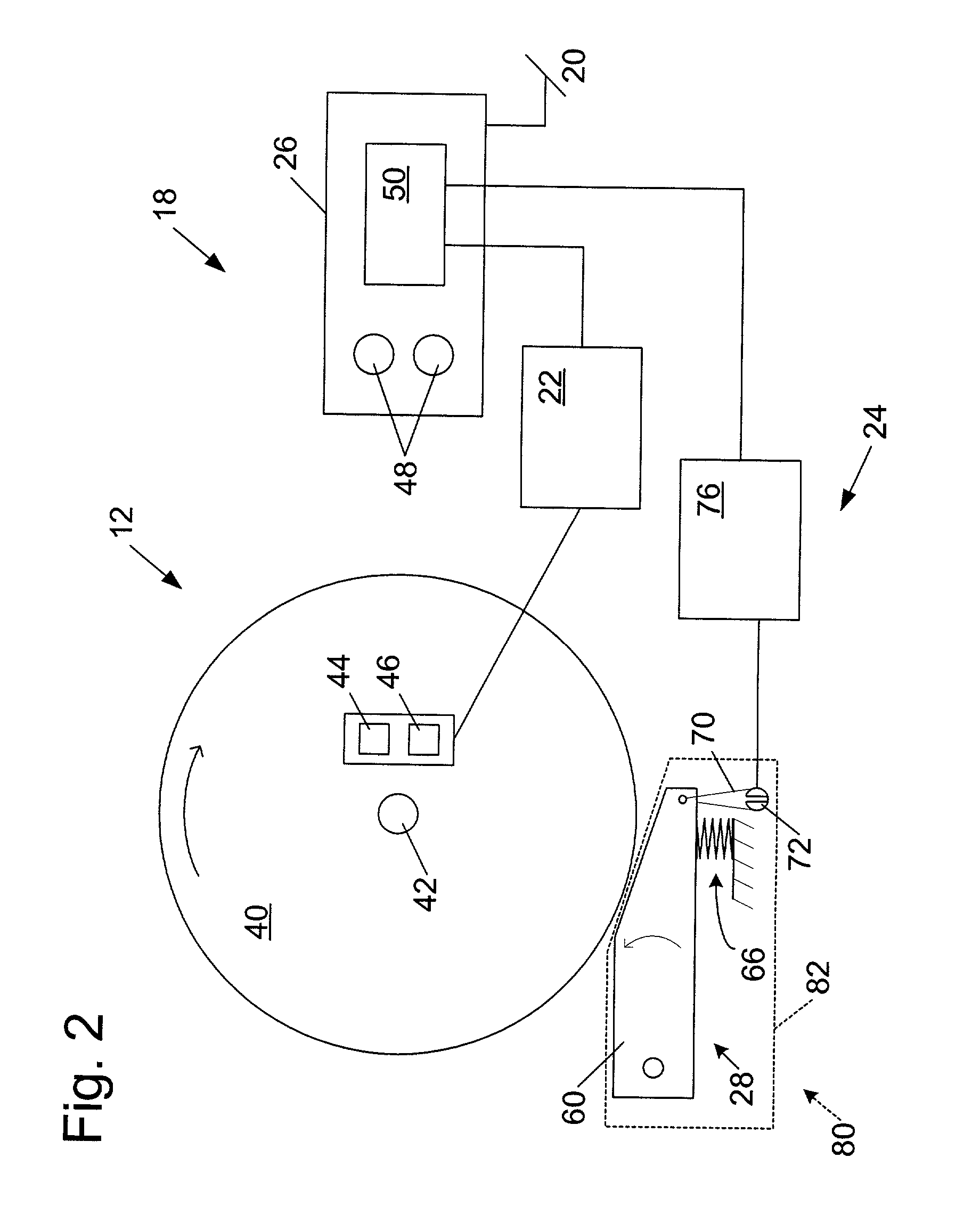
[0177] A machine embodying a safety system is shown schematically in FIG. 1 and indicated generally at 10. Machine 10 may be any of a variety of different machines adapted for cutting workpieces, such as wood, plastic, etc., including a table saw, miter saw, chop saw, radial arm saw, circular saw, band saw, jointer, planer, etc. Machine 10 includes an operative structure 12 having a cutting tool 14 and a motor assembly 16 adapted to drive the cutting tool. Machine 10 also includes a safety system 18 configured to minimize the potential of a serious injury to a person using machine 10. Safety system 18 is adapted to detect the occurrence of one or more dangerous conditions during use of machine 10. If such a dangerous condition is detected, safety system 18 is adapted to engage operative structure 12 to limit any injury to the user caused by the dangerous condition.
[0178] Machine 10 also includes a suitable power source 20 to provide power to operative structure 12 and safety system ...
PUM
Property
Measurement
Unit
Time
aaaaa
aaaaa
Abstract
Machines with safety systems are disclosed. The machine may take the form of woodworking machines including table saws, band saws, miter saws, hand-held circular saws, pneumatic chop saws, radial-arm saws, jointers, planars, routers and shapers. The machines may include an operative structure configured to perform a task, where the operative structure includes a cutting tool adapted to move in at least one motion, and a safety system adapted to detect the occurrence of an unsafe condition between a person and the cutting tool and for mitigating the unsafe condition. The safety system may include a detection subsystem and a reaction subsystem.
Description
[0001] This application claims the benefit of and priority from U.S. Provisional Patent Application Serial No. 60 / 275,583, filed Mar. 13, 2001, which is hereby incorporated by reference.[0002] This application hereby incorporates by reference the following U.S. patent application by reference: Ser. No. 09 / 676,190, filed Sep. 29, 2000. This application also hereby incorporates by reference the following PCT patent application: PCT / US00 / 26812, filed Sep. 29, 2000. This application further incorporates by reference the following U.S. provisional patent applications: Serial No. 60 / 157,340, filed Oct. 1, 1999; Serial No. 60 / 182,866, filed Feb. 16, 2000; Serial No. 60 / 225,056, filed Aug. 14, 2000; Serial No. 60 / 225,057, filed Aug. 14, 2000; Serial No. 60 / 225,058, filed Aug. 14, 2000; Serial No. 60 / 225,059, filed Aug. 14, 2000; Serial No. 60 / 225,089, filed Aug. 14, 2000; Serial No. 60 / 225,709, filed Aug. 14, 2000; Serial No. 60 / 225,069, filed Aug. 14, 2000; Serial No. 60 / 225,201, filed Aug...
Claims
Application Information
Patent Timeline
Application Date:The date an application was filed.
Publication Date:The date a patent or application was officially published.
First Publication Date:The earliest publication date of a patent with the same application number.
Issue Date:Publication date of the patent grant document.
PCT Entry Date:The Entry date of PCT National Phase.
Estimated Expiry Date:The statutory expiry date of a patent right according to the Patent Law, and it is the longest term of protection that the patent right can achieve without the termination of the patent right due to other reasons(Term extension factor has been taken into account ).
Invalid Date:Actual expiry date is based on effective date or publication date of legal transaction data of invalid patent.