Magnetic resonance system and method for comprehensive implantable device safety tests and patient safety monitoring

a magnetic resonance and comprehensive technology, applied in the field of magnetic resonance imaging and spectroscopy, can solve the problems of not being safe for mr imaging, difficult to determine whether or not the implant device is compatible with a given mr sequence, and diagnostic or clinical application of magnetic resonance, so as to reduce the likelihood of missing localized heating and rapid assessment

Inactive Publication Date: 2012-04-12
KONINKLIJKE PHILIPS ELECTRONICS NV
View PDF5 Cites 28 Cited by
  • Summary
  • Abstract
  • Description
  • Claims
  • Application Information

AI Technical Summary

Benefits of technology

[0010]One advantage resides in rapid assessment of incipient implant device heating over the entire volume of the implant device.
[0011]Another advantage resides in simultaneous real-time safety monitoring of all parts of the implant device.
[0012]Another advantage resides in providing safety monitoring with a reduced likelihood of missing localized heating.

Problems solved by technology

A difficulty with diagnostic or clinical application of magnetic resonance (MR) for imaging or the like is incompatibility with certain implant devices.
For example, an MR conditional device may be deemed safe for MR imaging employing a 1.5 Tesla magnetic field, but deemed not safe for MR imaging employing a 3 Tesla or higher magnetic field.
For MR sequence-dependent conditions, it may be difficult to determine whether or not the implant device is compatible with a given MR sequence performed using a particular set of sequence parameters.
Moreover, an MR conditional implant device that is generally considered to be safe for a given MR sequence operating with a given set of parameters may become unsafe if the implant device is somehow different from its assumed configuration.
For example, an MR conditional cardiac pacemaker that is safe for a given MR procedure may become unsafe if one of the electrical leads of the pacemaker is broken.
A principle risk in MR conditional or MR unsafe devices is that the electromagnetic fields generated by an MR procedure may induce electrical current flow in an electrically conductive portion of the implant device which may in turn lead to localized heating in the vicinity of the electrically conductive portion of the implant device.
Because the implant device is internal to the subject, it has heretofore been difficult or impossible to dynamically assess whether the MR is interacting with the implant device to generate an unsafe condition.
This approach has deficiencies.
For example, it increases complexity of the implant device, and also provides only a localized temperature measurement that may fail to detect localized heating of a part of the implant device located away from the temperature sensor.
Moreover, it is usually considered unsafe to allow any heating of the implant device in a patient, archaeological mummy, or other sensitive subject.
As a result, by the time the temperature sensor detects heating an unsafe condition may already exist.

Method used


Image

  • Magnetic resonance system and method for comprehensive implantable device safety tests and patient safety monitoring
  • Magnetic resonance system and method for comprehensive implantable device safety tests and patient safety monitoring
  • Magnetic resonance system and method for comprehensive implantable device safety tests and patient safety monitoring

Examples


Embodiment Construction

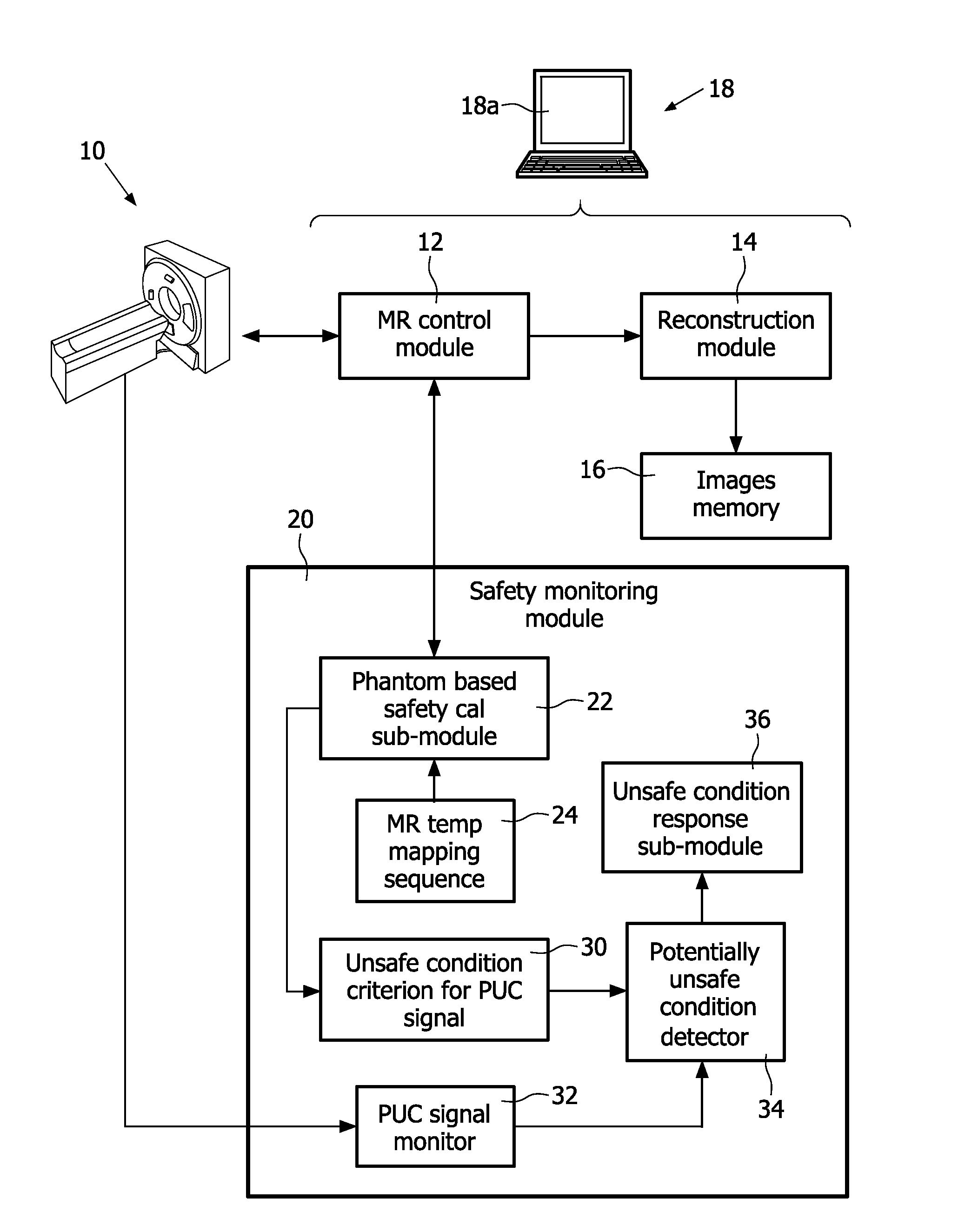
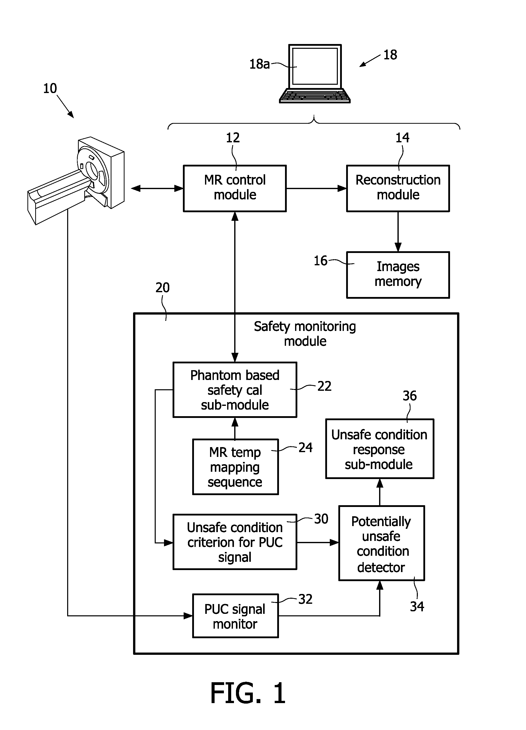
[0020]With reference to FIG. 1, a magnetic resonance system includes a magnetic resonance scanner 10, such as an illustrated Achieva™ magnetic resonance scanner (available from Koninklijke Philips Electronics N.V., Eindhoven, The Netherlands), or an Intera™ or Panorama™ magnetic resonance scanner (both also available from Koninklijke Philips Electronics N.V.), or another commercially available magnetic resonance scanner, or a non-commercial magnetic resonance scanner, or so forth. In a typical embodiment, the magnetic resonance scanner includes internal components (not illustrated) such as a superconducting or resistive main magnet generating a static (Bo) magnetic field, sets of magnetic field gradient coil windings for superimposing selected magnetic field gradients on the static magnetic field, a radio frequency excitation system for generating a radiofrequency (B1) field at a frequency selected to excite magnetic resonance (typically 1H magnetic resonance, although excitation of...


PUM


Abstract

A magnetic resonance method comprises: performing (C1) a magnetic resonance procedure on a calibration subject including an implant device; detecting (C2) a pick-up coil (PUC) signal at least during a radio frequency transmit phase of operation (C1); performing (C3) three dimensional temperature mapping of the calibration subject using a magnetic resonance sequence configured to detect any temperature change induced in any part of the implant device by operation (C1); generating (C4) an unsafe condition criterion (30) for the detected PUC signal based on correlating a PUC signal characteristic detected by operation (C2) with a temperature change detected by operation (C3); performing (M5) the magnetic resonance procedure on a subject containing an implant device; detecting (M6) a PUC signal at least during a radio frequency transmit phase of operation (M5); and monitoring (M7) for an unsafe condition indicated by the PUC signal detected in operation (M6) satisfying the unsafe condition criterion (30).

Description

FIELD OF THE INVENTION[0001]The following relates to the magnetic resonance arts. The following finds illustrative application to magnetic resonance imaging and spectroscopy, and is described with particular reference thereto. However, the following will find application in other magnetic resonance applications.BACKGROUND OF THE INVENTION[0002]A difficulty with diagnostic or clinical application of magnetic resonance (MR) for imaging or the like is incompatibility with certain implant devices. Such implant devices can be permanent or semi-permanent, such as a cardiac pacemaker, orthopedic joint implant, or the like; or can be a temporarily inserted implant device such as an interventional instrument (for example, a catheter or biopsy needle).[0003]For the purpose of MR safety, implant devices are typically classified as one of: “MR safe” which means the implant contains no metal or other electrically conductive material; “MR conditional” which means the implant contains at least som...

Claims


Application Information

Patent Timeline
Patent Type & Authority Applications(United States)
IPC IPC(8): G01R33/44G01R33/32
CPCG01R33/288G01R33/285
Inventor GRAESSLIN, INGMARKRUEGER, SASCHA
Owner KONINKLIJKE PHILIPS ELECTRONICS NV
Why Eureka
Try Eureka