Bladder pump for liquid sampling and collecting

a bladder pump and liquid sampling technology, applied in the direction of machines/engines, liquid fuel engines, positive displacement liquid engines, etc., can solve the problems of difficult transportation from one monitoring site to another, low efficiency of conventional bladder pumps, and low volume of liquid chambers 84, so as to prevent backflow, increase the length of the pump wall 32, and increase the volume of the liquid chamber 84

Inactive Publication Date: 2002-11-21
ANDERSON BRIAN
View PDF0 Cites 10 Cited by
  • Summary
  • Abstract
  • Description
  • Claims
  • Application Information

AI Technical Summary

Benefits of technology

0043] When the pumped liquid, such as groundwater, is flowing through the pump in the direction indicated by flow arrows 88, the groundwater passes through the outlet check valve 50 and through the outlet port 44 to the outlet fitting 14. The outlet check valve 50 in the top cap 40 substantially prevents backflow in the direction opposite that indicated by flow arrows 88. Correspondingly, the inlet cone-shaped check valve 90 prevents backflow of groundwater or other pumped liquid from the liquid chamber 84 through the axial communication passage 70 in the bottom bladder mandrel 66 into the inlet chamber 48.
0044] In operation, the fluid sampling pump 10 of the present invention is actuated by means of actuating gas supplied to the fluid chamber 86 which is alternately and sequentially subjected to positive and negative or reduced pressures. The alternate pressurizing and depressurizing of the actuating gas in the fluid chamber 86 causes the bladder 80 to alternately expand and contract, thus alternately and sequentially decreasing and increasing the volume of the liquid chamber 84. During such increases in volume, the groundwater is drawn from the well 2 into the liquid chamber 84 through the inlet apertures 39 in the casing 30 and the axial communication passage 70 in the bottom bladder mandrel 66. During such decreases in such volume, the groundwater is forced out of the liquid chamber 84 through the passage 56 in the top bladder mandrel 55 and the outlet port 44 in the top cap 40 and is passed through the outlet fitting 14 and the groundwater conduit 16 to be collected in the sample collection vessel 17. The check valves 50 and 90 prevent the water from being discharged through the inlet apertures 39 or drawing in through the outlet port 44.
0045] The capacity of the pump 10 may be changed in different versions of the pump by changing the diameter of the tubular pump casing 30, thereby changing the amount of water drawn in and forced out during the alternate contractions and relaxations of the flexible bladder 80. Preferably, the bladder pumps in accordance with the present invention is manufactured with the outside diameter 1.315". Theoretically, increasing the length of the pump wall 32 and correspondingly increasing the length of the bladder 50 would also increase the stroke volume. However, the longer pumps are subject to hang up in the non-plumb monitoring wells. For this reason, the bladder pumps for well monitoring ought to be designed as short as possible, such as 7.4".
0046] It should be noted that the various components of the pump 10, contacting the pumped liquid, are preferably composed of relatively lightweight and low-cost synthetic materials that will not be corroded when exposed to the groundwater and that will not otherwise affect the composition of the groundwater flowing through the pump. Examples of such materials include stainless steel, rigid polyvinyl chloride (PVC), DELRIN and polytetrafluoroethylene (PTFE) marketed under the DuPont Teflon.RTM. trademark. The flexible bladder 80 is preferably composed of a flexible synthetic material that also will not corrode or affect the composition of groundwater flowing therethrough, such as PTFE, or Teflon.RTM.. The casing 30 of the pump is preferably made of PVC. The ball members 54 and 98 of the ckeck valves 50 and 90 respectively, are preferably made of PTFE, or Teflon.RTM.. One skilled in the art will readily recognize, however, that the various components of the fluid sampling apparatus may be composed of other suitable non-corrosive materials.
0047] Therefore, the novel arrangement of the liquid sampling bladder pump of the present invention as constructed in the above-described embodiments provides simplified field application and easy deployment in non-plumb wells, and allows for obtaining representative samples of groundwater or other liquids.

Problems solved by technology

Current portable equipment for the groundwater sampling is relatively heavy, bulky, and thus difficult to transport from one monitoring site to another.
The conventional bladder pumps have proven to be not very efficient, however, in obtaining consistent, non-contaminated water samples that are accurately representative of the water system from which the sample is taken.
The inadequacies of previous sampling equipment stem largely from such causes as cross-contamination between sampling sites, ineffective and inconsistent field cleaning methods, contamination due to equipment handling, and inconsistent well depth sampling.
In addition to presenting sample quality problems, much of the previous equipment has been heavy and bulky and thus difficult to transport from one monitoring site to another.
Moreover, conventional bladder pumps for groundwater sampling have proved to be complicated to operate, relatively expensive, and impractical for sampling at remote locations where site access is severely limited.

Method used


Image

  • Bladder pump for liquid sampling and collecting
  • Bladder pump for liquid sampling and collecting
  • Bladder pump for liquid sampling and collecting

Examples


Embodiment Construction

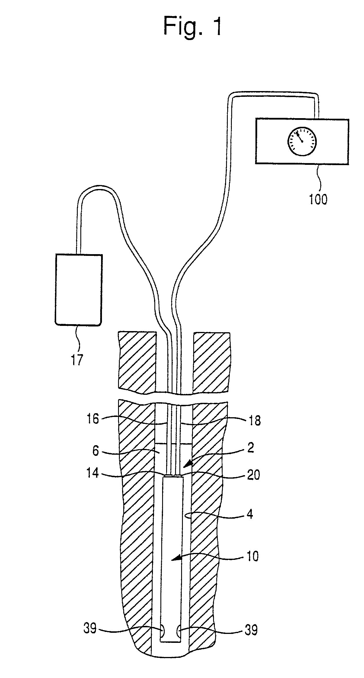
[0021] FIG. 1 of the drawings illustrates an underground liquid sampling system of the present invention indicated generally by reference numeral 1. For purposes of illustration, the liquid sampling apparatus is shown as installed in a monitoring well 2. A liquid sampling pump 10 is disposed within the well casing 4 of the monitoring well 2 and is submerged beneath the level of the groundwater 6 to a suitable depth for obtaining representative groundwater samples.

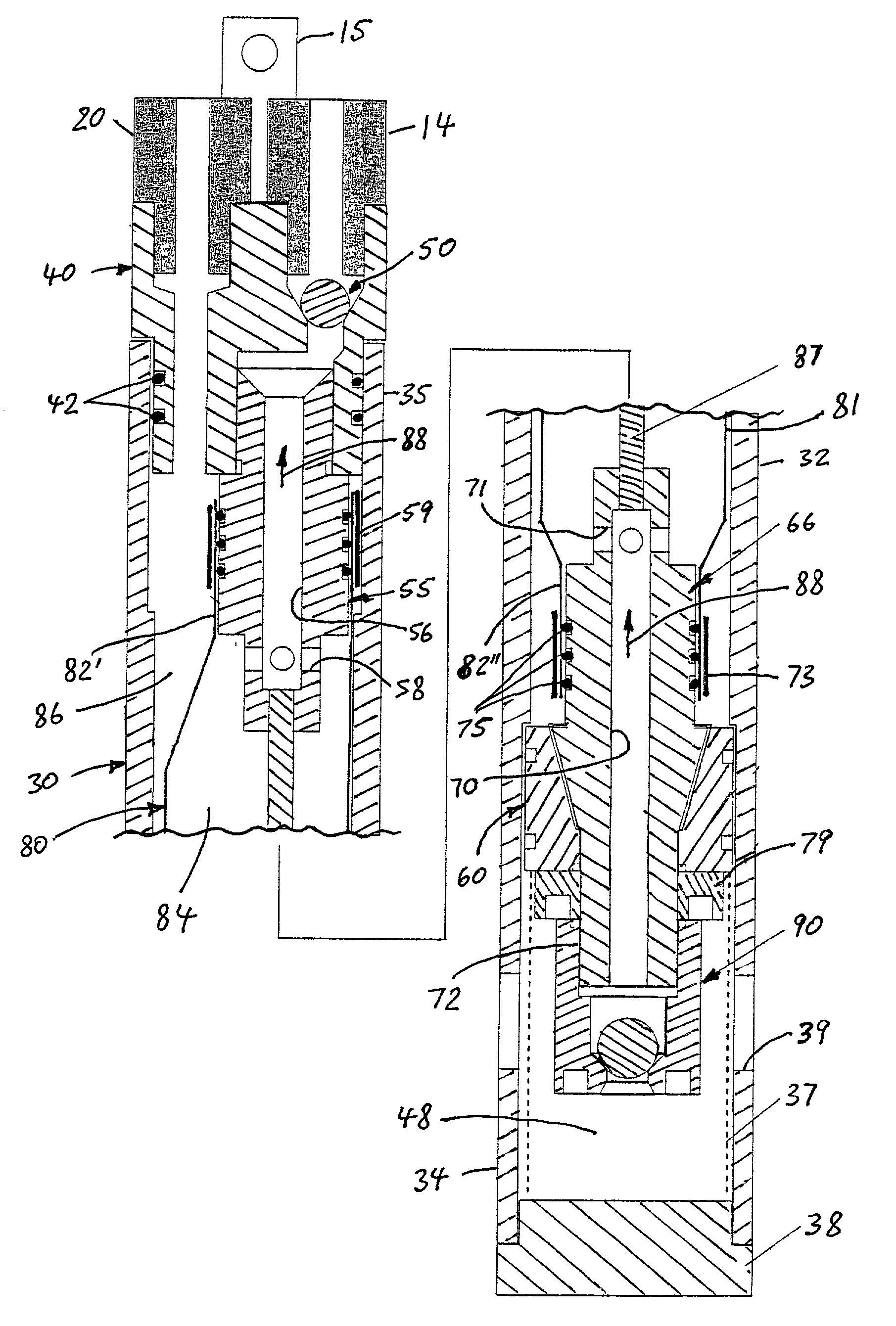
[0022] As is explained in further detail below, the liquid sampling pump 10 in accordance with the present invention, is a bladder-type fluid-actuated pump, wherein the actuating fluid is a pressurized gas, preferably compressed air, and includes a plurality of inlet openings 39, an outlet fitting 14, and a fluid fitting 20.

[0023] A liquid conduit 16 is sealingly connected at one end to the pump outlet fitting 14 to provide direct sample delivery to a sample collection vessel 17. A pressurized gas conduit 18 is connected at...


PUM


Abstract

A liquid pump for pumping groundwater samples from small diameter sub-terrain wells, comprising a tubular casing having inlet apertures, a top cap provided with a fluid communication port and a liquid outlet port, a top bladder mandrel secured to the top cap, a mandrel sealing member disposed in a lower end of the casing, a bottom bladder mandrel secured to the mandrel sealing member, and a flexible bladder extending between the top bladder mandrel and the bottom bladder mandrel and defining a liquid chamber for receiving the liquid therein and a fluid chamber for receiving a fluid under pressure therein that surrounds the liquid chamber, with the bladder disposed therebetween. The fluid chamber is in fluid communication with the fluid communication port connected to a source of the actuating gas, while the liquid chamber is in one-way fluid communication with the liquid inlet and the liquid outlet port.

Description

[0001] This is a continuation-in-part of U.S. application Ser. No. 09 / 512,295, filed Feb. 24, 2000, allowed.[0002] 1. Field of the Invention[0003] The present invention relates generally to liquid pumping and collecting apparatuses, and more particularly to a bladder pump for pumping underground liquid, such as groundwater samples, from small diameter wells. It should be noted, however, that the invention is also applicable and adaptable in various other applications that will occur to one skilled in the art from the disclosure herein.[0004] 2. Description of the Prior Art[0005] Recent increases in public concern for the environment have resulted in various government-imposed environmental regulations with regard to groundwater quality and land-site cleanup projects. Among such regulations are requirements relating to the monitoring and sampling of water quality of aquifers as sources of drinking water. In response to these requirements, water quality analytic capabilities have been...

Claims


Application Information

Patent Timeline
Patent Type & Authority Applications(United States)
IPC IPC(8): F04B47/04
CPCF04B47/04
Inventor ANDERSON, BRIAN
Owner ANDERSON BRIAN
Why Eureka
Try Eureka