Method for controlling operating of switched reluctance motor (SRM)

a technology of switched reluctance motors and operating methods, which is applied in the direction of motor/generator/converter stoppers, electronic commutators, dynamo-electric converter control, etc., can solve the problems of difficult setting of standard values (a standard rpm or standard current value) and the stop of srm

Inactive Publication Date: 2002-11-28
LG ELECTRONICS INC
View PDF0 Cites 3 Cited by
  • Summary
  • Abstract
  • Description
  • Claims
  • Application Information

AI Technical Summary

Benefits of technology

0016] Therefore, an object of the present invention is to provide a method for controlling operating of a Switched Reluctance Motor (SRM) capable of operating the SRM according to a phase under the normal condition in case a noise is inputted to a position sensor in the SRM from the outside.

Problems solved by technology

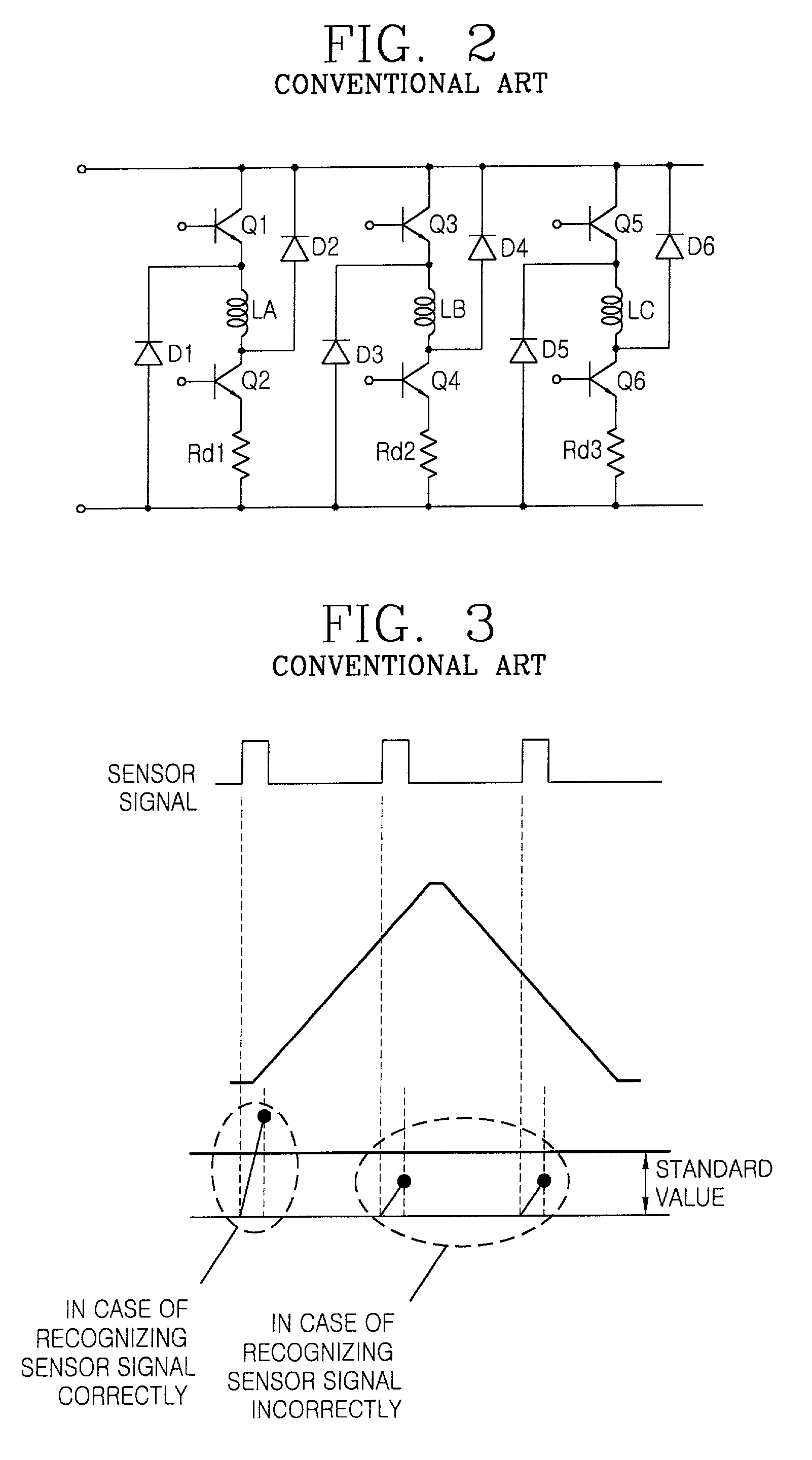
Particularly, in case the speed of the SRM must be changed according to the status of load, there occurs a problem that setting of the standard value (a standard RPM or a standard current value) is difficult.
Also, in the conventional method for controlling operating of the SRM, there occurs a problem that the SRM is stopped if inertia of load is small in case the SRM is operated shifting the phase when the noise is inputted in the SRM.

Method used


Image

  • Method for controlling operating of switched reluctance motor (SRM)
  • Method for controlling operating of switched reluctance motor (SRM)
  • Method for controlling operating of switched reluctance motor (SRM)

Examples


Embodiment Construction

[0034] Reference will now be made in detail to the preferred embodiments of the present invention, examples of which are illustrated in the accompanying drawings.

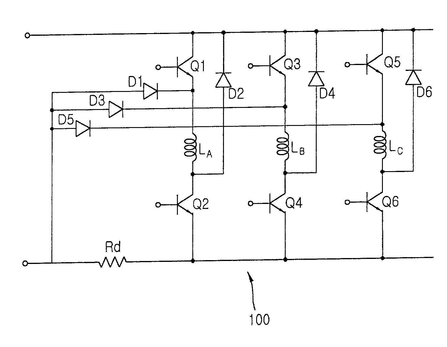
[0035] Hereinafter, a method for controlling operation of a Switched Reluctance Motor to operate the SRM normally according to a phase under the normal condition in case a noise is inputted to a position sensor in the SRM will be described with reference to FIGS. 4 to 13.

[0036] FIG. 4 is a view showing inductance of respective phases according to the position of a rotor of the three phase SRM of 12 / 8 structure.

[0037] As shown in FIG. 4, an inductance for phases applied to a winding in the SRM is determined by the relative position of a stator and a rotor in the SRM. At this time, since the voltage equation in case the SRM is under the condition of being stopped is V=Ldi / dt, a current flowing in each phase applied to the winding in the SRM is expressed as follows.

I=.intg.V / L dt formula 1

[0038] Here, the above V is voltage ap...


PUM


Abstract

A method for controlling driving of a Switched Reluctance Motor (SRM) is capable of operating the SRM normally according to a phase under the normal state in case a noise is inputted to a position sensor in the SRM. In order to achieve the advantage, the method for controlling driving of a three phase SRM using a position sensor having a rate of a rotor and a stator is {fraction (6/4)} or {fraction (12/8)} includes the steps of generating a sensor signal according to the position of a rotor in the SRM and operating the SRM by turning on respective phases in the SRM at the point of detecting a rising edge of the sensor signal and turning off the phase at the point of detecting a falling edge of the next sensor signal.

Description

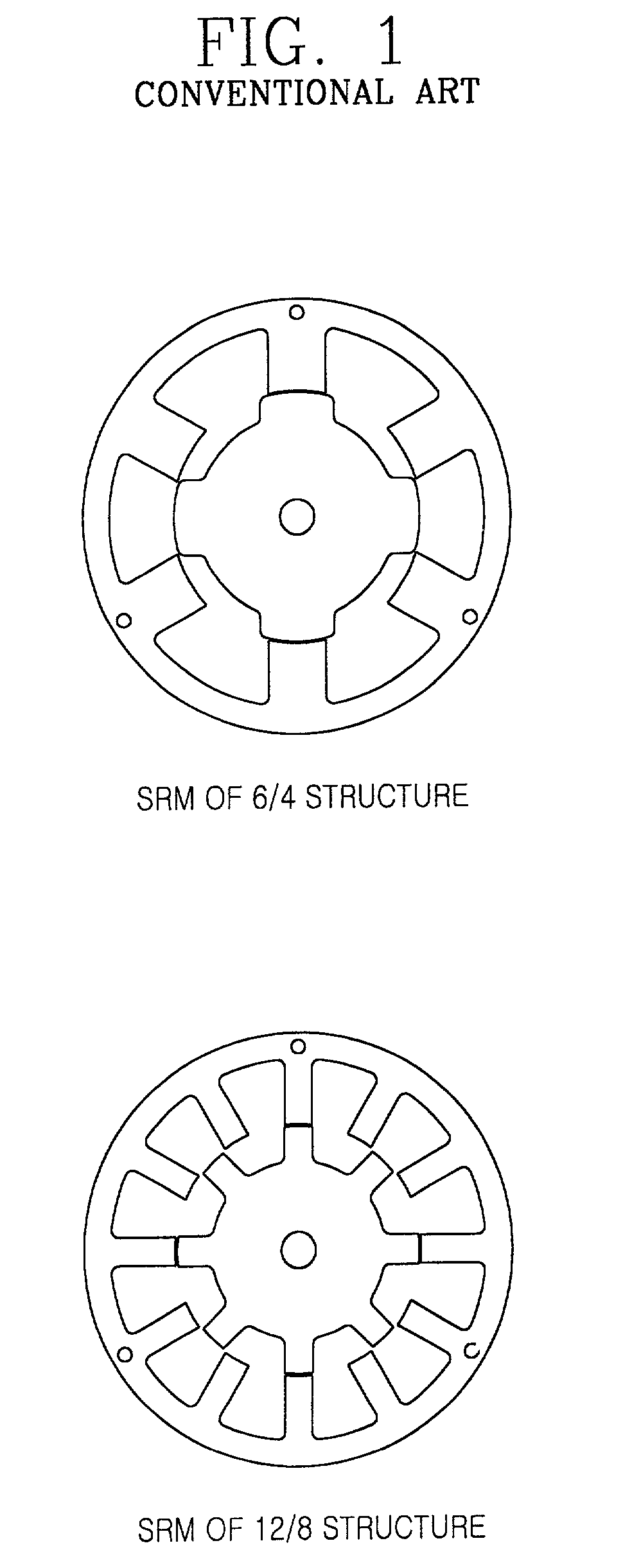
BACKGROUND OF THE INVENTION[0001] 1. Field of the Invention[0002] The present invention relates to a method for controlling operating of a Switched Reluctance Motor (SRM), particularly, to a method for controlling operating of a SRM to drive the SRM according to a phase under the normal condition in case a noise is inputted from the outside.[0003] 2. Description of the Background Art[0004] FIG. 1 is a schematic view showing 6 / 4 and 12 / 8 structures of a conventional Switched Reluctance Motor (SRM) in accordance with the conventional art.[0005] As shown in FIG. 1, a conventional SRM is composed of a SRM having 6 / 4 and 12 / 8 structures and a circuit for operating the SRM and detecting a current flowing in the respective phases applied to a winding in the SRM. Here, the circuit will be described with reference to FIG. 2 as follows.[0006] FIG. 2 is a circuit diagram for detecting a current applied to the conventional SRM.[0007] As shown in FIG. 2, the circuit for detecting the current app...

Claims


Application Information

Patent Timeline
Patent Type & Authority Applications(United States)
IPC IPC(8): H02P25/08
CPCH02P25/08H02P6/16H02P25/0925H02P6/185
Inventor KIM, SANG YOUNGLIM, JUN YOUNG
Owner LG ELECTRONICS INC
Why Eureka
Try Eureka