Method and apparatus for controlling electromagnetic driving valve for internal combustion engine

Inactive Publication Date: 2002-12-12
MITSUBISHI ELECTRIC CORP
View PDF6 Cites 6 Cited by
  • Summary
  • Abstract
  • Description
  • Claims
  • Application Information

AI Technical Summary

Benefits of technology

[0010] The present invention has been developed to solve the above mentioned problems, and aims at obtaining a method and an apparatus capable of starting an engine with a starter motor having a small output torque, and controlling the electromagnetic valve for an internal combustion engine not requiring a recess in the piston.

Problems solved by technology

That is, a starter motor controlled by an inverter is limited in output torque by the capacity of the power element.
As a result, an internal combustion engine only having such a starter cannot be satisfactorily used.
In addition, if the cranking process is performed with the valve opened, the interference between the intake and exhaust valve and the piston cannot be avoided as pointed out by the above described Japanese Patent Laid-Open No. 9-303122, thereby requiring a recess in the piston to avoid the interference.
Furthermore, when the cranking process is performed with the valve opened, a pumping loss occurs.

Method used


Image

  • Method and apparatus for controlling electromagnetic driving valve for internal combustion engine
  • Method and apparatus for controlling electromagnetic driving valve for internal combustion engine
  • Method and apparatus for controlling electromagnetic driving valve for internal combustion engine

Examples


first embodiment

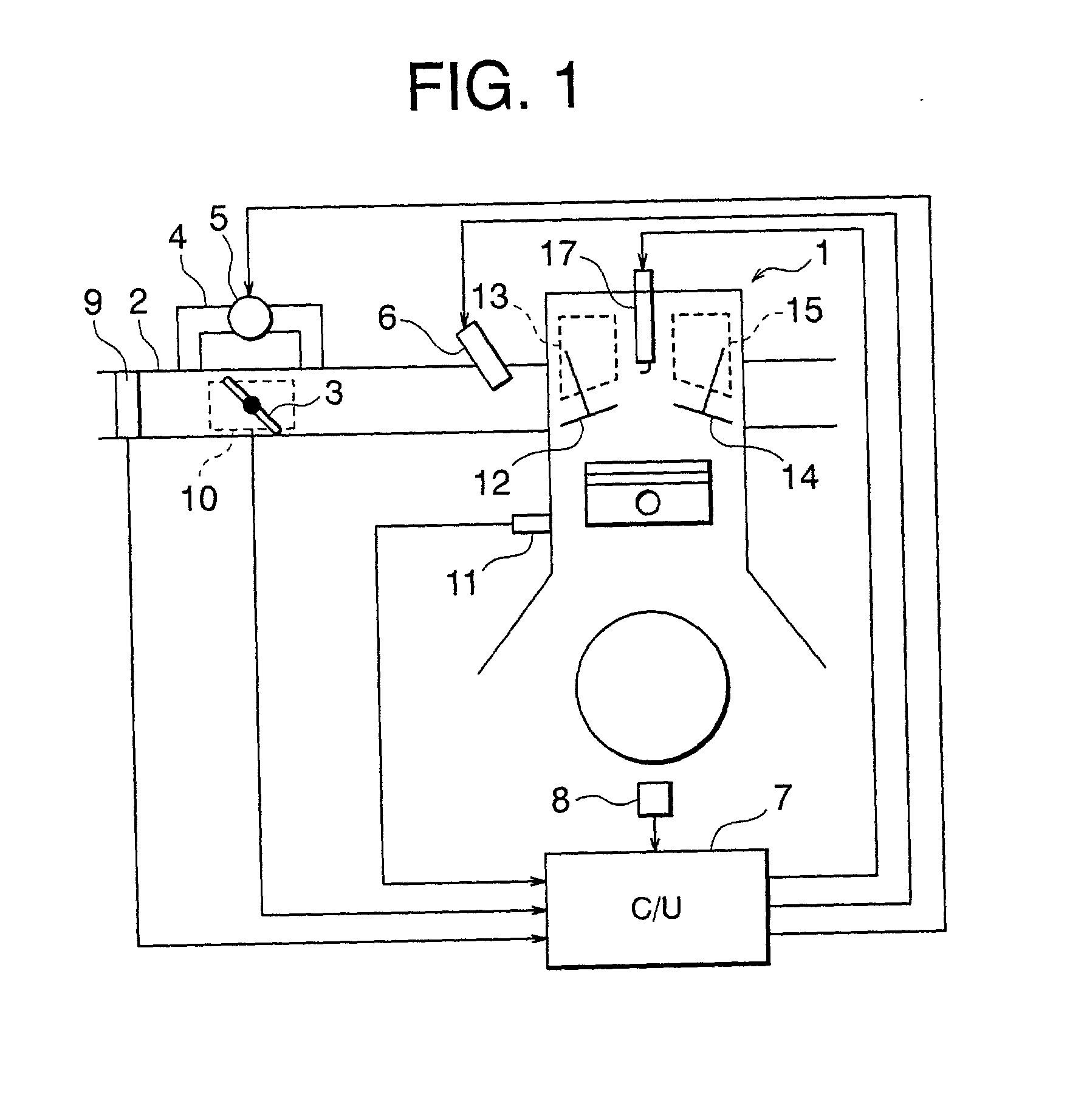
[0036] FIG. 1 shows a configuration of a system of an internal combustion engine according to the present invention.

[0037] In FIG. 1, an intake path 2 of a 4-cycle internal combustion engine 1 is provided with a throttle valve 3 and an auxiliary air path 4 for bypassing the throttle valve 3. The auxiliary air path 4 is provided with an electromagnetic auxiliary air control valve 5.

[0038] When the 4-cycle internal combustion engine 1 is an engine (for example, a mirror cycle engine, etc.) capable of, for example, controlling the open / close period of an intake valve 12 by an electromagnetic driving valve device (electromagnetic driving valve) 13 described later to take in the air in an atmospheric pressure and control the amount of intake air without a throttle valve, the throttle valve 3, the auxiliary air path 4 and the auxiliary air control valve 5 can be omitted.

[0039] Furthermore, the intake port unit of the intake path 2 is provided with an electromagnetic fuel jet valve 6 for e...

embodiment 2

[0066] FIG. 9 shows a configuration of a second embodiment of the present invention. In FIG. 9, the same or corresponding portions shown in FIG. 1 are assigned the same reference numerals, and the detailed explanation is omitted here.

[0067] In FIG. 9, reference numeral 28 denotes a starter motor, and receives power from a battery 30 through drive means 27 as first starter control means.

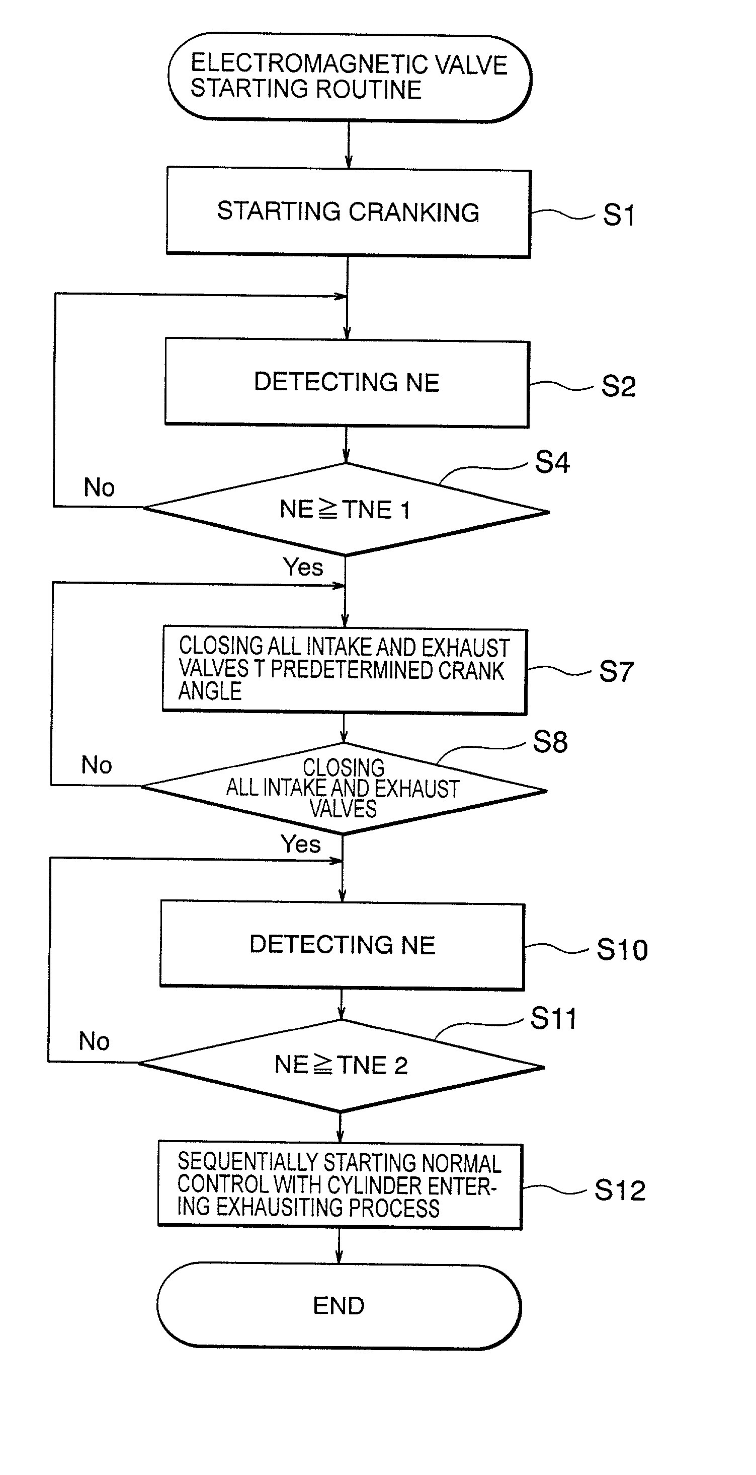
[0068] Then, the procedure of the process of the electromagnetic driving valve starting routine will be described below by referring to the flowchart shown in FIG. 10.

[0069] In step S1, the starter motor 28 is turned on, and the cranking is started. Then, in step S2, the rotating speed of the crank shaft, that is, the cranking speed NE is detected based on the output of the crank angle sensor 8. In step S4, it is determined whether or not the cranking speed NE has exceeded the first predetermined rotating speed TNE1. If the determination result is YES, then control is passed to step S6, and the starte...

embodiment 3

[0074] FIG. 11 shows a the configuration showing a third embodiment of the present invention. In FIG. 11, the same or corresponding portions as in FIG. 1 are assigned the same reference numerals, and the explanation is omitted here.

[0075] In FIG. 11, reference numeral 28 denotes a starter motor to which power is applied from the battery 30 through the drive means 27. Reference numeral 29 denotes current detection means for detecting the current provided to the starter motor 28. The drive means 27 and current detection means 29 configure the second starter control means.

[0076] Then, the procedure of the process of the electromagnetic driving valve starting routine is described below by referring to the flowchart shown in FIG. 12.

[0077] First, in step S1, the starter motor 28 is turned on, and the cranking is started. Then, in step S2, the rotating speed of the crank shaft, that is, the cranking speed NE, is detected based on the output of the crank angle sensor 8. In step S3, the loa...


PUM


Abstract

An engine with an electromagnetic driving valve reduces a loss during a cranking operation to shorten a starting time, reduce an electric power consumption for a starter motor, and prevent an interference between a valve system and a piston. Intake and exhaust valves are sequentially excited and started such that, after starting the cranking operation by a starter motor, a first cranking rotating speed can be reached, and the valves can be all closed at a predetermined cranking angle. All intake and exhaust valves are closed and the cranking rotating speed reaches an ignition point by the supply of a fuel and the continuous operation of the engine can be performed at more than a second cranking rotating speed, and the intake and exhaust valves can be switching controlled in the normal cylinder process.

Description

[0001] 1. Field of the Invention[0002] The present invention relates to a method and an apparatus for controlling an electromagnetic driving valve for an internal combustion engine for use as an intake and exhaust valve in an internal combustion engine, and more specifically to the electromagnetic valve driving control technology in starting the engine.[0003] 2. Description of the Prior Art[0004] It has been conventionally known that an electromagnetic valve is designed to displace an intake and exhaust valve supported in a neutral position with elasticity using a spring between an all-closed position and an all-opened position by using the electromagnetic force. Furthermore, various methods such as a starting sequence, etc. have been disclosed for starting control of an electromagnetic valve for use in starting an engine.[0005] In the method of starting an electromagnetic valve, as described in Japanese Patent Laid-Open No. 9-303122, an electromagnetic valve initially in the neutra...

Claims


Application Information

Patent Timeline
IPC IPC(8): F01L9/04F01L13/00F02D13/02F02D41/20F02N19/00
CPCF02N19/004
Inventor OGAWA, KENJIWACHI, SATOSHI
Owner MITSUBISHI ELECTRIC CORP
Why Eureka
Try Eureka