Multi-channel magnetic tape system having optical tracking servo

a multi-channel magnetic tape and optical tracking technology, applied in the direction of maintaining the head carrier alignment, disposing/mounting the head, instruments, etc., can solve the problems of inability to follow the tape accurately enough to provide reliable performance, and the problem of tracking errors is a major source of tracking errors

Inactive Publication Date: 2002-12-12
QUANTUM CORP
View PDF99 Cites 35 Cited by
  • Summary
  • Abstract
  • Description
  • Claims
  • Application Information

AI Technical Summary

Problems solved by technology

Because of a relatively high linear tape velocity, and because tape substrates continue to be made thinner and thinner, guiding tape past a tape head structure along an accurate invariant linear path has proven to be highly problematical.
LTM is a major source of tracking errors in linear tape recording.
Unfortunately, a limiting factor is LTM, and at some track width dimension and track density, it is not possible to follow the tape accurately enough to provide reliable performance.
These tapes are known in the art as "preformatted" tapes, and the step of recording accurate servo tracks onto the tape is both time consuming and expensive.
While these prior methods and approaches have worked within their intended applications and uses, improvements and simplifications in the medium and drive apparatus have been lacking.

Method used


Image

  • Multi-channel magnetic tape system having optical tracking servo
  • Multi-channel magnetic tape system having optical tracking servo
  • Multi-channel magnetic tape system having optical tracking servo

Examples


Embodiment Construction

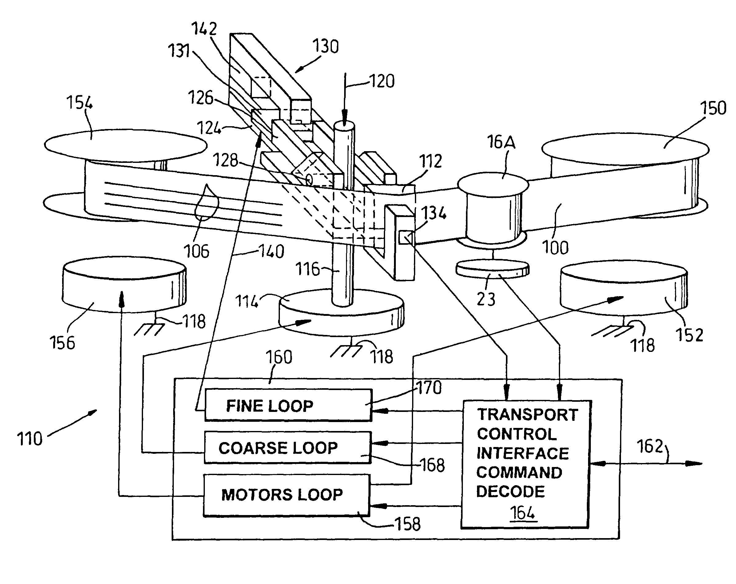
[0027] Referring initially to FIG. 1, a magnetic recording tape 100 is shown being drawn through a tape drive mechanism 110 from a supply reel to a take-up reel (not shown) along a nominal linear tape path indicated by arrow TP. The tape 100 is moved at a considerable linear relative velocity, such as 150 inches per second. Because of this high relative velocity and contact between the tape 100 and mechanical tape guide and head elements of the tape drive 110, the linear movement of the tape 100 along the nominal tape path TP results in certain undesirable additional tape movements, a principal one of which being lateral tape motion ("LTM") or motion transverse to the nominal tape path as indicated by arrow LTM.

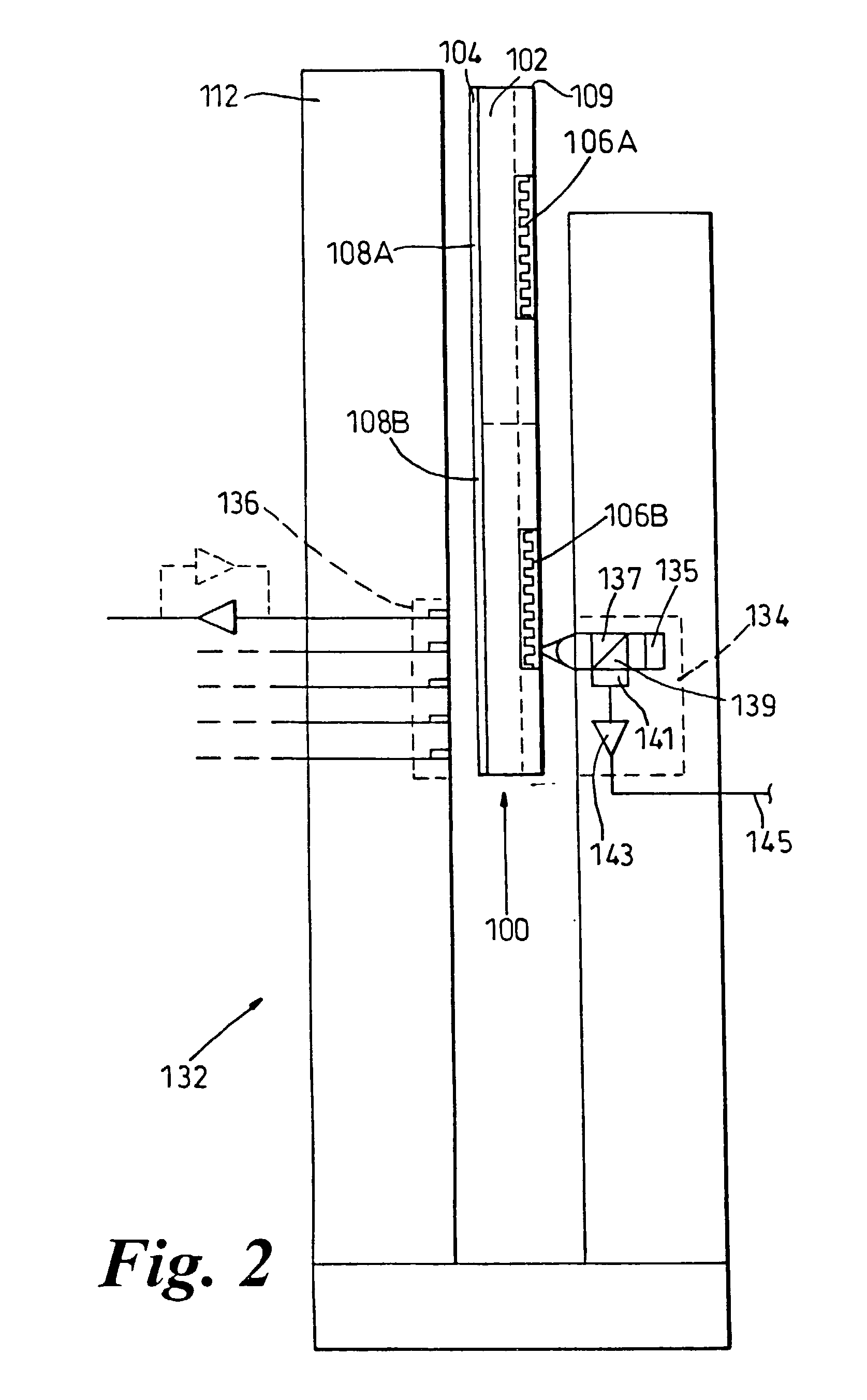
[0028] As discussed above, although mechanical steps are known to reduce LTM, at certain high linear track densities and narrow track widths it is not practical to rely entirely upon open loop tape mechanisms. Accordingly, the magnetic recording tape 100 includes, in addition...


PUM

PropertyMeasurementUnit
linear relative velocityaaaaaaaaaa
flexibleaaaaaaaaaa
widthaaaaaaaaaa

Abstract

A magnetic storage medium formed on a front major surface of a tape substrate defines a multiplicity of longitudinal data recording and playback tracks, each track having a nominal lateral location relative to the other tracks: and a predetermined optically manifested track servo pattern defined on the back major surface of the tape for indicating lateral displacement of the tape from a nominal lateral location of the track during tape movement across a read / write head. A magnetic tape recording and playback system employing the magnetic storage medium is also disclosed.

Description

REFERENCE TO RELATED APPLICATION[0001] The present invention is related to commonly assigned, copending U.S. patent application Ser. No. ______, filed on the same day as this provisional patent application for: "Dual-Actuator Pivoting Lever Tape Head Positioner", George A. Saliba, Inventor, (Quantum Docket No. Q98-1087-US1), the disclosure thereof being incorporated herein by reference.[0002] The present invention relates to magnetic tape recording. More particularly, the present invention relates to a multi-channel magnetic tape recording system employing an optical tracking servo to sense and correct for lateral tape motion, and lateral track motion, as the tape is drawn longitudinally across a head transducer assembly.[0003] Digital tape recording remains a viable solution for storage of massive amounts of data. Conventionally, at least two approaches are employed for recording of digital information onto magnetic recording tape. One approach calls for moving the tape past a rota...

Claims


Application Information

Patent Timeline
Patent Type & Authority Applications(United States)
IPC IPC(8): G11B5/78G11B5/584G11B5/592G11B5/73G11B7/09G11B21/10
CPCG11B5/5926
Inventor SALIBA, GEORGE A.MALLICK, SATYA A.KIM, CHANTURGEON, CAROLCAPPABIANCA, LEOCRONIS, LEWIS
Owner QUANTUM CORP
Why Eureka
Try Eureka