Method for improving acoustic properties of a terminal device and a terminal device

a terminal device and acoustic technology, applied in the direction of antennas, frequency/directions obtaining arrangements, transmission, etc., can solve the problems of improving leakage tolerance especially in small devices, affecting the acoustic quality of terminal devices, etc., to achieve good leakage tolerance, improve acoustic properties of terminal devices, and maintain good sound quality

Inactive Publication Date: 2002-12-12
FLEXTRONICS SALES & MARKETING A P
View PDF5 Cites 45 Cited by
  • Summary
  • Abstract
  • Description
  • Claims
  • Application Information

AI Technical Summary

Benefits of technology

0008] The objective of the invention is to improve the acoustic properties of terminal devices such as mobile stations by achieving a leakage tolerance as good as possible for them, i.e. a capability to maintain the sound quality good, although the properties of the acoustic space between the speaker and the ear change while the distance between them changes. The present invention provides a method for improving acoustic properties of a terminal device of a telecommunication network and a terminal device of a telecommunication network.

Problems solved by technology

In case the leakage is strong, the user will perceive changes in the quality of the sound reaching his or her ear, since low frequencies tend to weaken more than high frequencies.
The problem referred to above can be encountered especially in mobile stations and corresponding terminal devices, since the aforementioned devices are typically not pressed, and they cannot necessarily be pressed, tight against the ear.
The improving of the leakage tolerance especially in small devices is problematic, since the devices typically have little space in order that the solutions improving the leakage tolerance could be easily introduced.

Method used


Image

  • Method for improving acoustic properties of a terminal device and a terminal device
  • Method for improving acoustic properties of a terminal device and a terminal device
  • Method for improving acoustic properties of a terminal device and a terminal device

Examples


Embodiment Construction

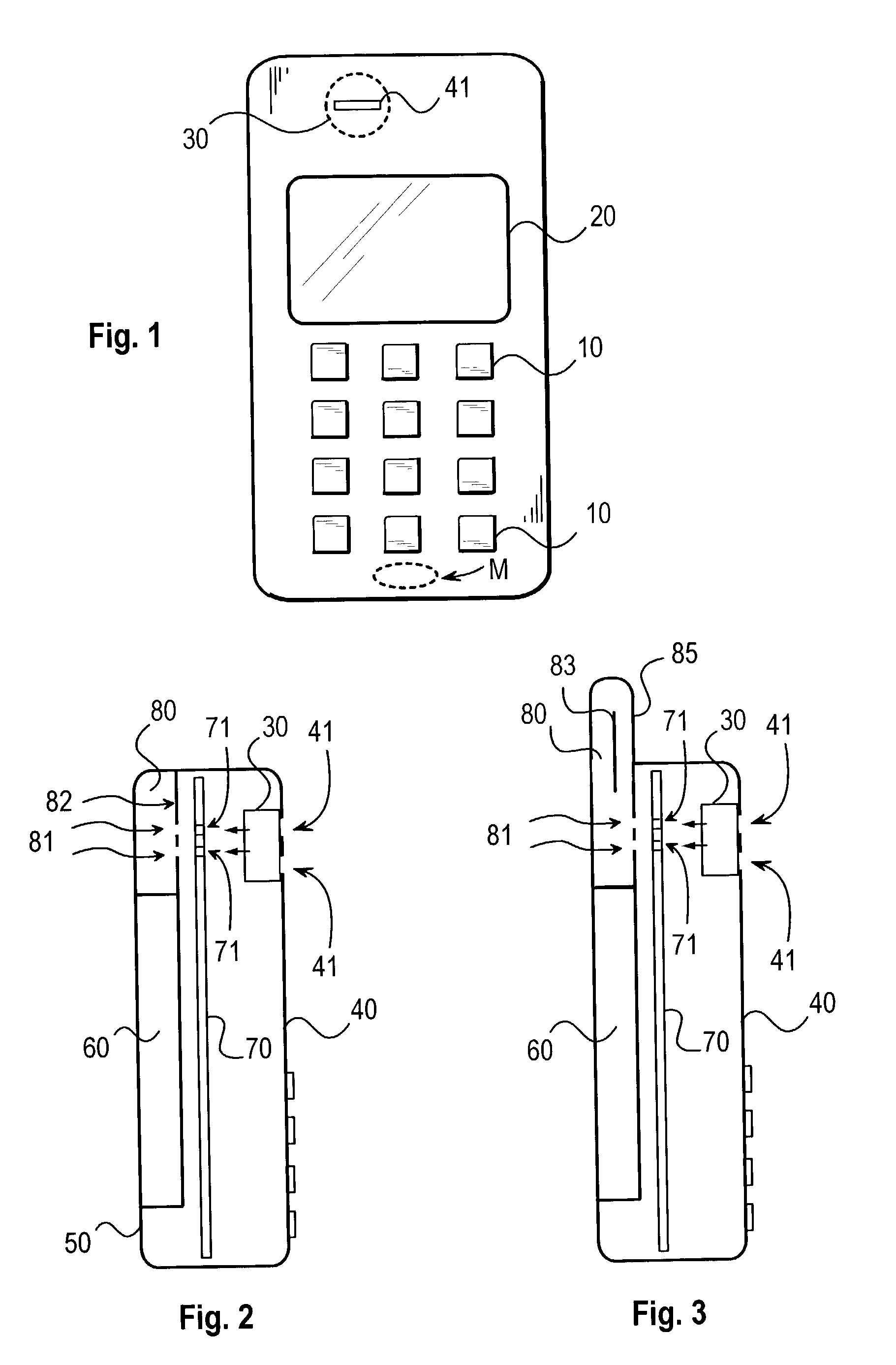
[0033] FIG. 1 represents the subscriber terminal device of the invention as seen from the front. As can be seen in the figure, the subscriber terminal device comprises keys 10, a display 20 and a speaker 30, which converts an electronic signal into an acoustic sound. In the implementation mode of FIG. 1, the speaker is located in the upper part of the device above the display. Correspondingly, the microphone M is typically located in the lower part of the device below the keyboard. This is a common implementation mode e.g. in mobile stations. When the user of a terminal device such as this is in a speech connection, he or she can hear the audio signal generated by the speaker of the subscriber terminal device the better the closer he or she keeps the speaker to his or her ear.

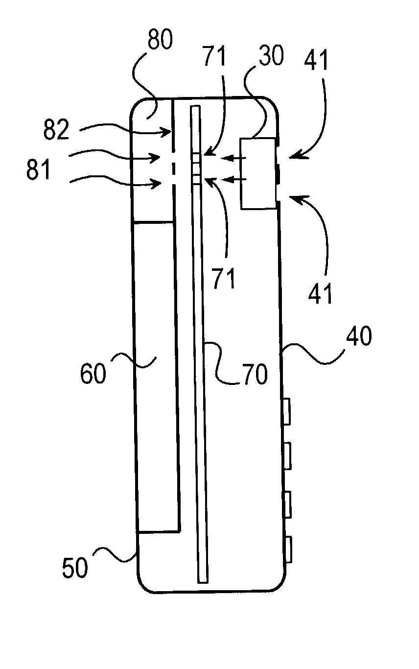
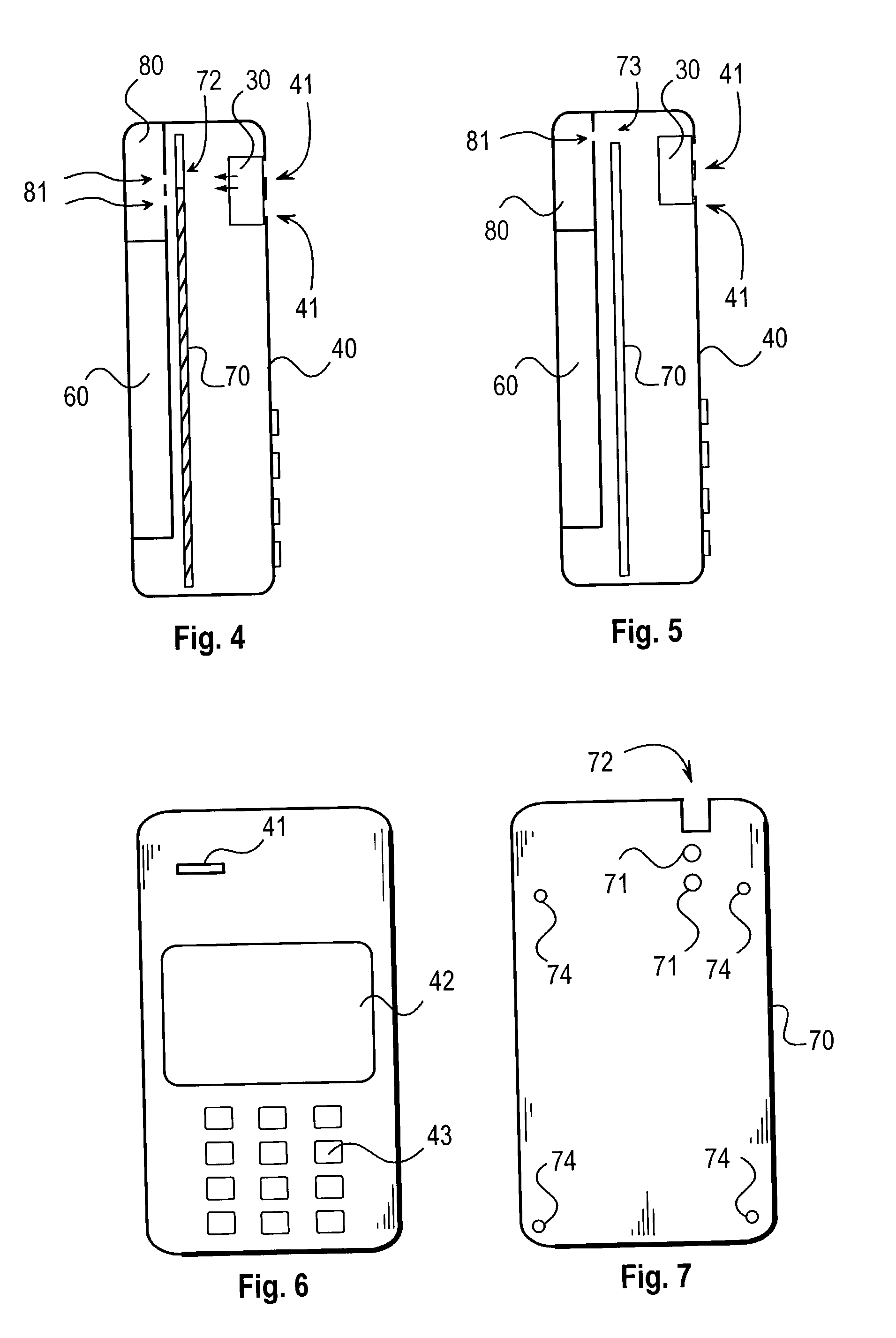
[0034] FIG. 2 illustrates one implementation mode of the terminal device as seen simplified from the side. The terminal device comprises a speaker 30, front part 40 of the cover and at least one hole 41 in it t...


PUM


Abstract

The present invention relates to acoustic properties of a terminal device of a telecommunication network. To improve the capability of the terminal device to maintain the sound quality good while the distance between the speaker and the ear changes, the enclosure of the terminal device is provided with means (71, 81) for conveying the acoustic waves generated backwards by the speaker (30) of the device inside the enclosure to a cavity-like antenna space (80) intended for the antenna of the terminal device.

Description

[0001] The invention relates to the acoustic properties of a terminal device and particularly to the ones of a subscriber terminal device of a telecommunication system such as a mobile station. More particularly, the objective of the invention is to improve the capability of a terminal device to maintain the acoustic properties of sound while the distance between the speaker or receiver (e.g. transducer) of the terminal device and the ear is growing.[0002] In order that the user of a terminal device would hear a sound as optimal as possible as regards its strength and quality, the speaker of the device must usually be held against the ear as close as possible. In other words, normally the user experiences that he or she hears the best sound in respect of quality when the terminal is pressed tightly against the ear, in which case a kind of an acoustic, sealed space is created between the mobile station and the ear.[0003] If the speaker is not pressed against the ear, a gap is created...

Claims


Application Information

Patent Timeline
Patent Type & Authority Applications(United States)
IPC IPC(8): H01Q1/24H04B1/38H04M1/03
CPCH01Q1/242H04M1/03H04B1/3833H04M1/0202H04R1/02H04R1/20
Inventor YLITALO, JUHAKAUPPINEN, ANTTI-OLLI
Owner FLEXTRONICS SALES & MARKETING A P
Why Eureka
Try Eureka