Low slope dispersion managed waveguide

Inactive Publication Date: 2002-12-19
CORNING INC
View PDF3 Cites 15 Cited by
  • Summary
  • Abstract
  • Description
  • Claims
  • Application Information

AI Technical Summary

Problems solved by technology

When bit rate is increased beyond 2.5 Gb/s, fiber dispersion has been a major degradation for long distance.
On the other

Method used


Image

  • Low slope dispersion managed waveguide
  • Low slope dispersion managed waveguide
  • Low slope dispersion managed waveguide

Examples


Embodiment Construction

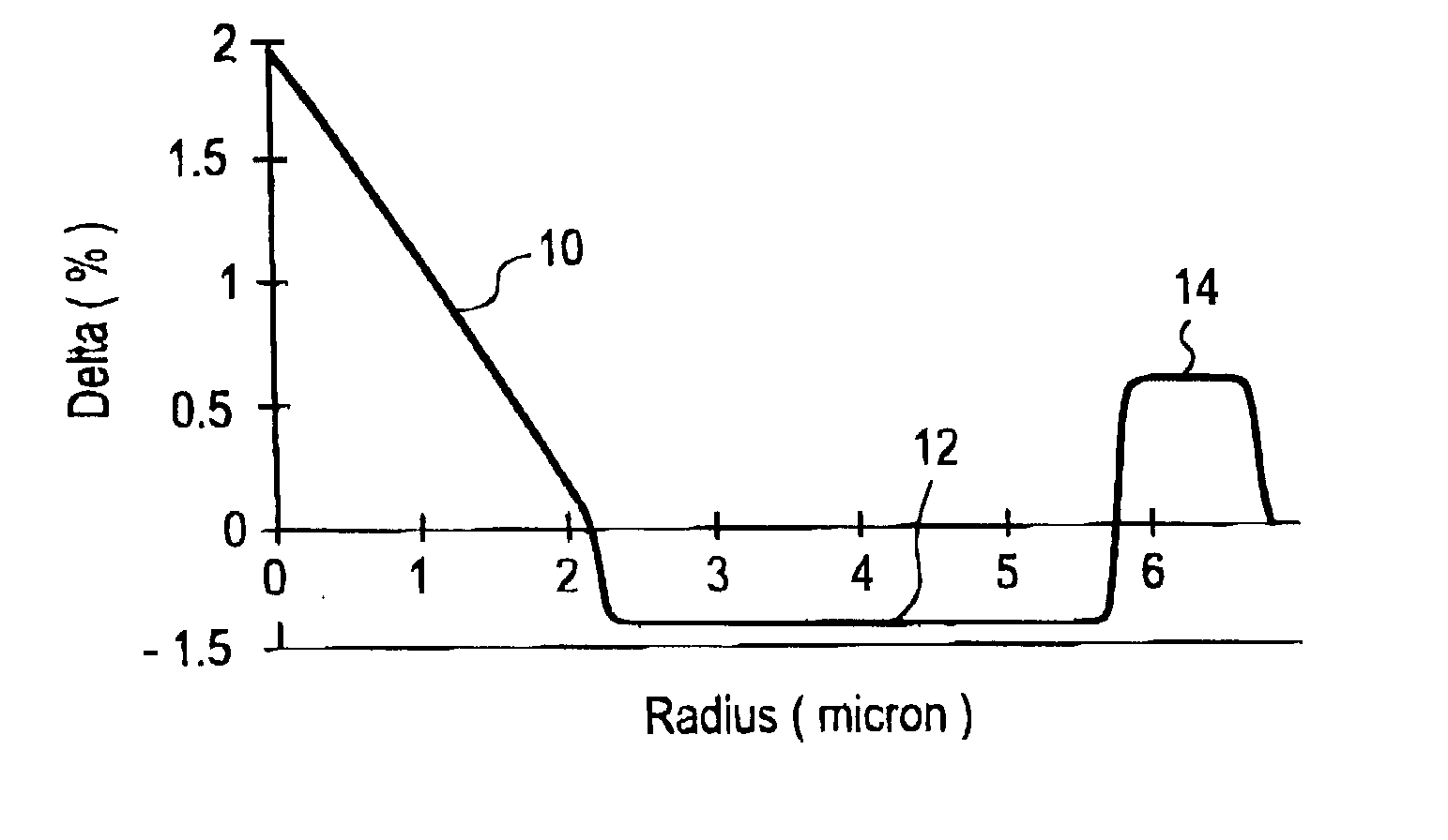
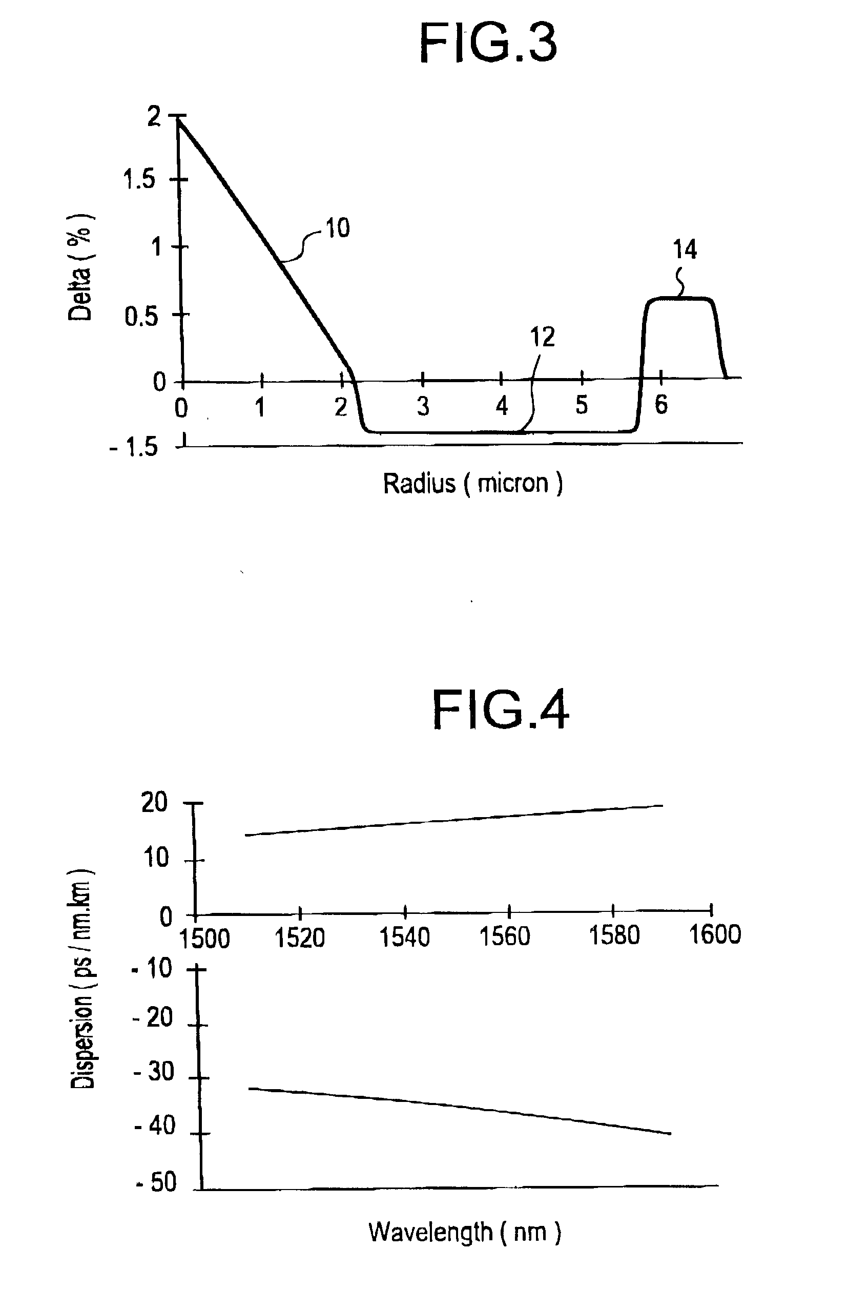
[0060] A particularly preferred three segment refractive index profile for use as the negative dispersion, negative slope fiber segment is illustrated in FIG. 3. This particular profile exhibits a dispersion of -35.47 ps / nm.multidot.km and slope of --0.1018 ps / nm.sup.2.multidot.km at 1550 nm. The cutoff wavelength is 1.18 micron and pin-array bend loss of 1.3 dB, MFD of 4.8 micron and Deff of 4.68 micron at 1550 nm.

[0061] FIG. 4 illustrates the dispersion characteristics of achieved when a positive dispersion fiber component, in this case SMF-28, is combined with the negative dispersion fiber component of the variety disclose in FIG. 3 variety having the following parameters:

3 Delta (%) Radius (.mu.m) Core 2 2.2 (r.sub.1) First moat -0.4 5.76 (r.sub.2) Ring 0.6 6.72 (r.sub.3)

[0062] Table III below lists the resultant dispersion and dispersion slope properties, as well as the ratio of dispersion to dispersion slope which is achieved by this combination of alternating fiber segments.

4...


PUM


Abstract

Disclosed is a single mode optical waveguide fiber having alternating segments of positive and negative dispersion and dispersion slope. The relative indexes, the refractive index profiles and the radii of the segments are chosen to provide low total dispersion and dispersion slope. Preferred waveguides in accordance with the invention exhibit a dispersion over the range of 1520 to 1625 nm which at all times has a magnitude which is less than 2, and more preferably less than 1 ps/nm2-km. The total dispersion of the waveguide fiber is in the range of about -2.0 to +2.0 ps/nm-km at 1550 nm. The waveguide also features a low polarization mode dispersion.

Description

[0001] This application claims the benefit of the filing date of U.S. Provisional Application Nos. 60 / 075,754, filed Feb. 23, 1998, and 60 / 088,023, filed Jun. 4, 1998.[0002] 1. Field of the Invention[0003] The present invention is directed to a single mode optical waveguide fiber designed for long repeater spacing, high data rate telecommunication systems. In particular, the single mode waveguide combines excellent bend resistance, low attenuation, low dispersion and low dispersion slope, features that are desired for long distance transmission applications.[0004] 2. Technical Background[0005] The requirement in the telecommunication industry for greater information capacity over long distances, without electronic signal regeneration, has led to a reevaluation of single mode fiber index profile design.[0006] Recent developments in erbium-doped fiber amplifiers (EDFAs) and wavelength division multiplexing have enabled high-capacity lightwave systems. In order to achieve high capacity...

Claims


Application Information

Patent Timeline
IPC IPC(8): G02B6/34
CPCG02B6/02238G02B6/02247G02B6/02261G02B6/03688G02B6/0281G02B6/03644G02B6/03666G02B6/02285
Inventor LIU, YANMING
Owner CORNING INC
Why Eureka
Try Eureka