Methods and apparatus for transferring electrical components

Inactive Publication Date: 2002-12-19
DELAWARE CAPITAL FORMATION
View PDF0 Cites 20 Cited by
  • Summary
  • Abstract
  • Description
  • Claims
  • Application Information

AI Technical Summary

Problems solved by technology

Since wafers and dies are not of uniform size, it may be necessary to change to a larger or smaller vacuum spindle tip when picking up larger or smaller dies.
For example, the elevator accepts only one size of film frame, which means that wafers of different size cannot be simultaneously accommodated in the machi

Method used


Image

  • Methods and apparatus for transferring electrical components
  • Methods and apparatus for transferring electrical components
  • Methods and apparatus for transferring electrical components

Examples


Embodiment Construction

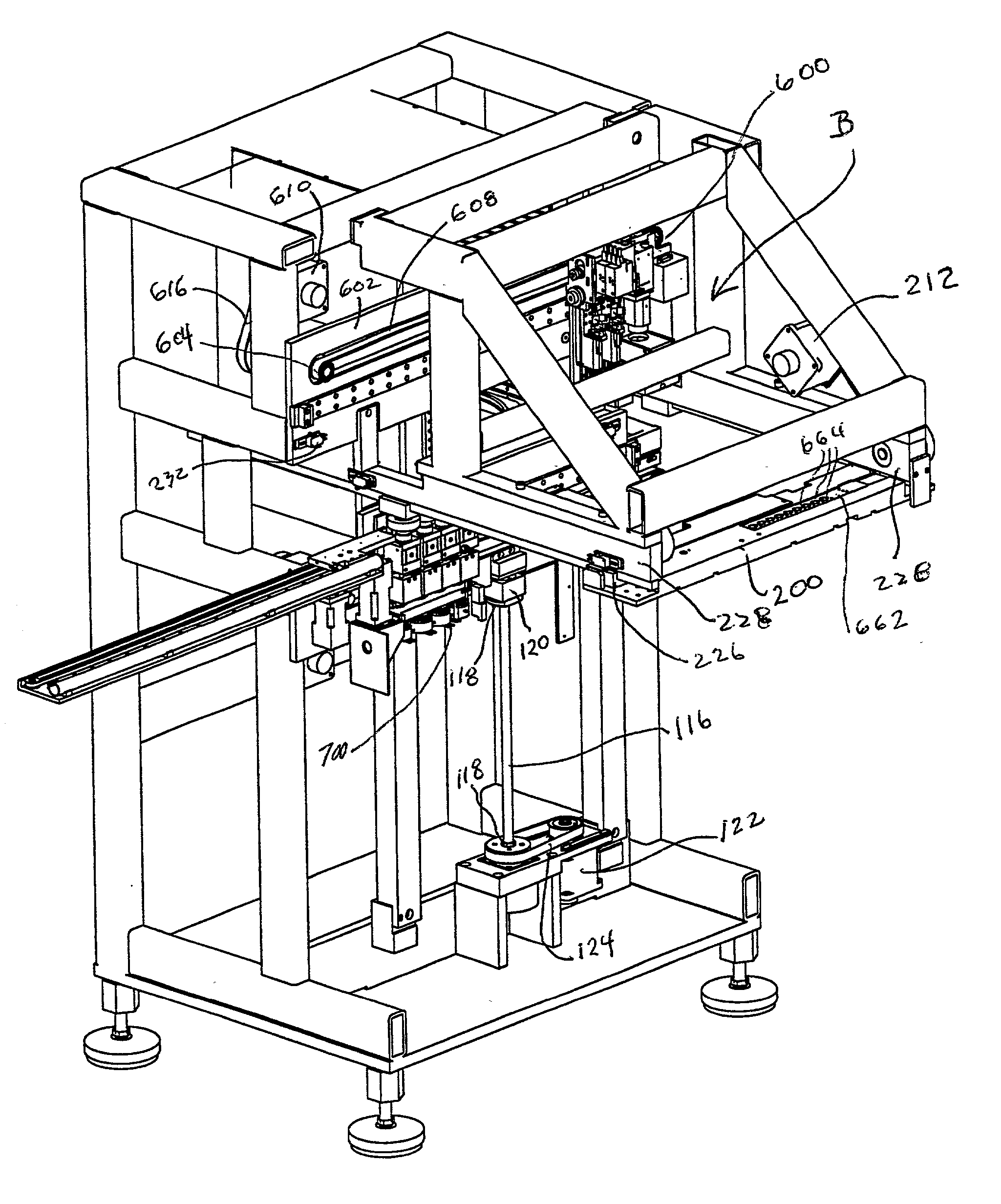
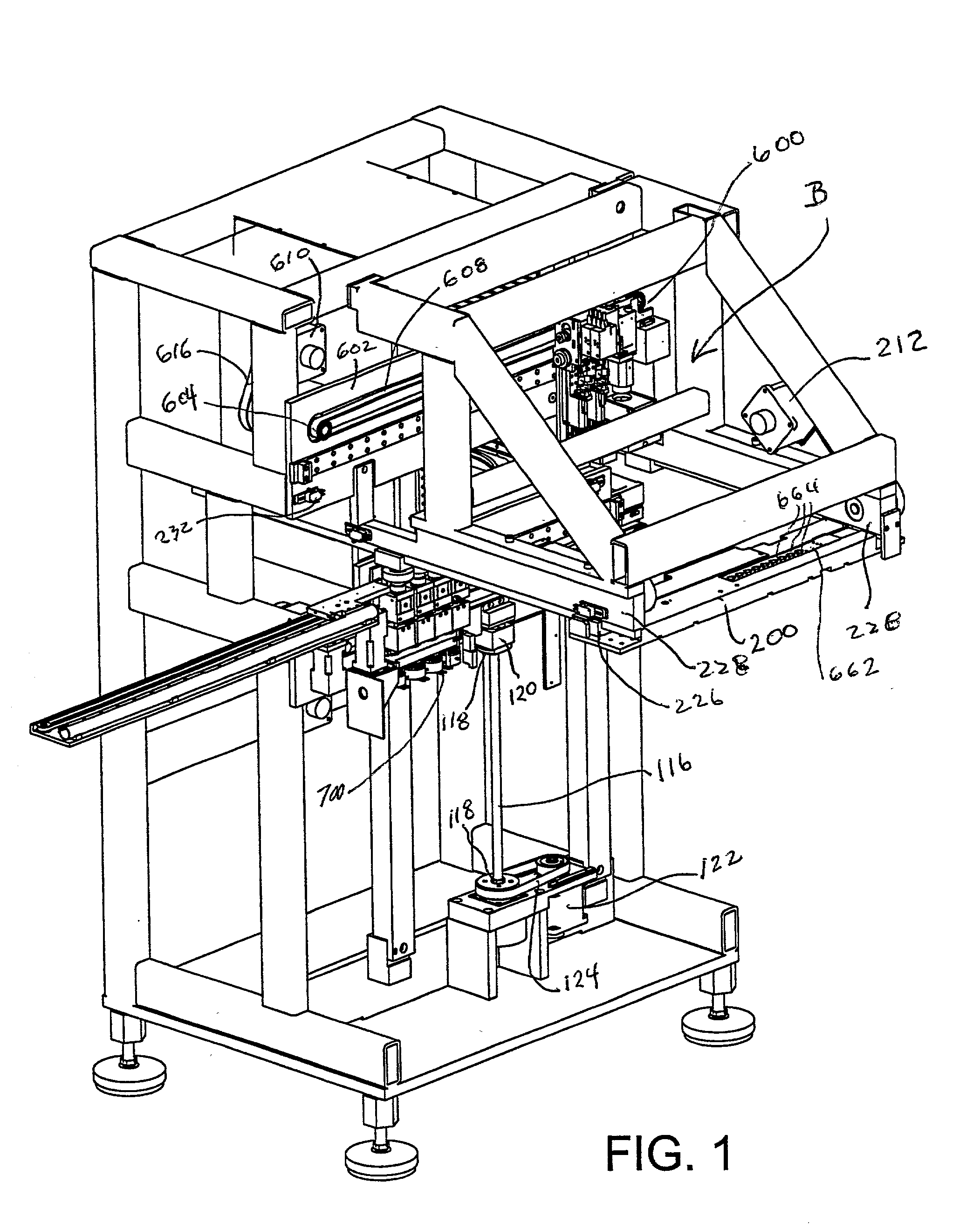
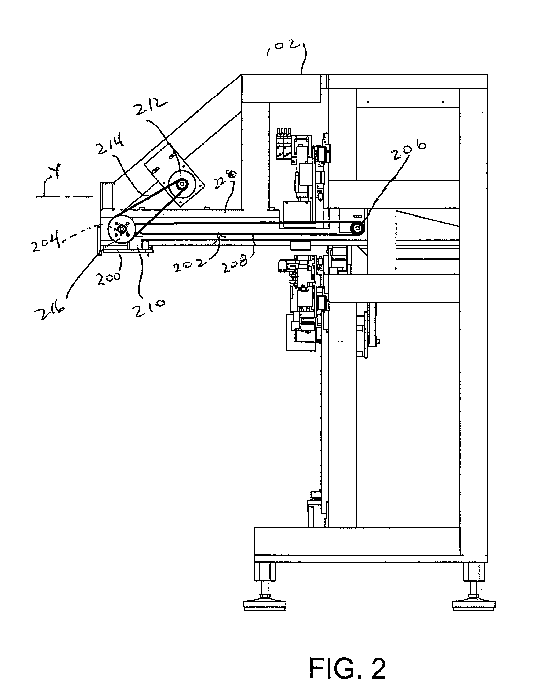
[0043] An apparatus for removing individual dies from a semiconductor wafer comprises a wafer feed section A in which a plurality of wafers are provided, a pick and place section B where individual dies are removed from the wafers, and a receiver section C where the removed dies are deposited for further handling.

[0044] Wafer Feed Section

[0045] The wafer feed section A comprises a stationary base frame 102 to which an elevator 104 is mounted for up / down movement (see FIG. 3). The elevator includes a pair of parallel vertical side walls 106 of identical configuration. The side walls are interconnected by top and bottom walls 108, 110 to form a rigid structure.

[0046] Each side wall 106 includes an inner surface in which are formed a plurality of parallel, horizontally extending slots 112 or 112' spaced equidistantly apart in the vertical direction. The slots 112 on one side wall are horizontally aligned with, and arranged parallel to, respective ones of the slots 112' formed on the ot...


PUM

PropertyMeasurementUnit
Sizeaaaaaaaaaa
Distanceaaaaaaaaaa

Abstract

A mechanism for handling semiconductor wafers includes a feed section which comprises a vertically movable elevator able to hold a number of vertically spaced carriers. Each carrier has a film frame mounted thereon for supporting a wafer. A pulling mechanism pulls a selected carrier out of the elevator along a first axis and into a pick and place section. A transfer mechanism removes individual dies from the wafer and moves them to a flip station along a second axis oriented perpendicularly to the first axis. The transfer mechanism can move different distances along the second axis to be able to remove dies arranged in a row along the second axis. The flip station is driven by a single motor to both lower and invert the dies.

Description

[0001] 1. Field of the Invention[0002] The present invention relates generally to the transfer of electrical components and in particular to methods and apparatus for handling semiconductor wafers, particularly the removal of individual dies from semiconductor wafers and a transferring of such dies.[0003] 2. Description of Related Art[0004] In the manufacture of electrical devices, it is conventional to pre-cut a semiconductor wafer into rows of individual components called "dies." The dies are then individually removed and transferred for assembly into a chip package or multi-chip module.[0005] It is conventional to perform such die removal and transfer operations by an automated machine. Such a machine can include a wafer feed section where a plurality of wafers are stored, a pick and place section for transferring individual dies from the wafers, and a receiver section in the form of a flip station which receives and inverts the dies.[0006] At the feed section each wafer is adhes...

Claims


Application Information

Patent Timeline
IPC IPC(8): H01L21/00H01L21/677H01L21/687
CPCH01L21/67132H01L21/67144Y10T29/53178H01L21/68728H01L21/67346
Inventor FOSTER, JAMES E. JR.ASHMAN, DAMONJANISIEWICZ, STANLEYBURGIN, JOHN JR.TOKARZ, RONALD
Owner DELAWARE CAPITAL FORMATION
Why Eureka
Try Eureka