
Device for purifying exhaust gas of engines

a technology for exhaust gas and engine, applied in the direction of exhaust treatment electric control, electrical control, separation process, etc., can solve the problems of increased smoke emission, unfavorable engine output drop, and reduced precision

Inactive Publication Date: 2002-12-26
DENSO CORP
View PDF1 Cites 73 Cited by
  • Summary
  • Abstract
  • Description
  • Claims
  • Application Information

AI Technical Summary

Problems solved by technology

When the particulate matter is deposited to an excess degree, the particulate filter of this type loses the permeability in the exhaust gas passage, causing an undesired drop in the engine output and an increased emission of smoke.
When it is attempted to detect the exhaust gas pressure and the differential pressure between the upstream and the downstream of the particulate filter in an averaged manner, however, an averaging error occurs due to pulsation in the exhaust pipe resulting in a decrease in the precision.
When there exists pulsation, the average values thereof deviate from a static secondary functional relationship to develop an average error.
That is, even though it is attempted to find a differential pressure (.DELTA.) between the upstream and the downstream sides of the particulate filter corresponding to the average value of the exhaust gas flow rate (G), the value that is obtained tends to become large and involve an error.
Even though it is attempted to effect the on-board diagnosis (OBD) function, therefore, it is not possible to detect the values when the apparent passage area is abnormally large or it is not possible to change, while maintaining a sufficient degree of reliability, the method of burning the particulate matter and regenerating the particulate filter in compliance with a decrease in the apparent passage area.
Under the conditions where the flow rate of the air taken in by the automotive engine is small such as under an idling condition, the differential pressure between the upstream and the downstream sides of the particulate filter becomes very small, and the apparent passage area is not found sufficiently precisely.
When the PM is deposited to an excess degree on the DPF 21 of the above-mentioned type, the exhaust gas passage loses the permeability, resulting in a decrease in the engine output and an increase in the emission of smoke which is harmful.

Method used


Image

  • Device for purifying exhaust gas of engines
  • Device for purifying exhaust gas of engines
  • Device for purifying exhaust gas of engines

Examples


Embodiment Construction

]

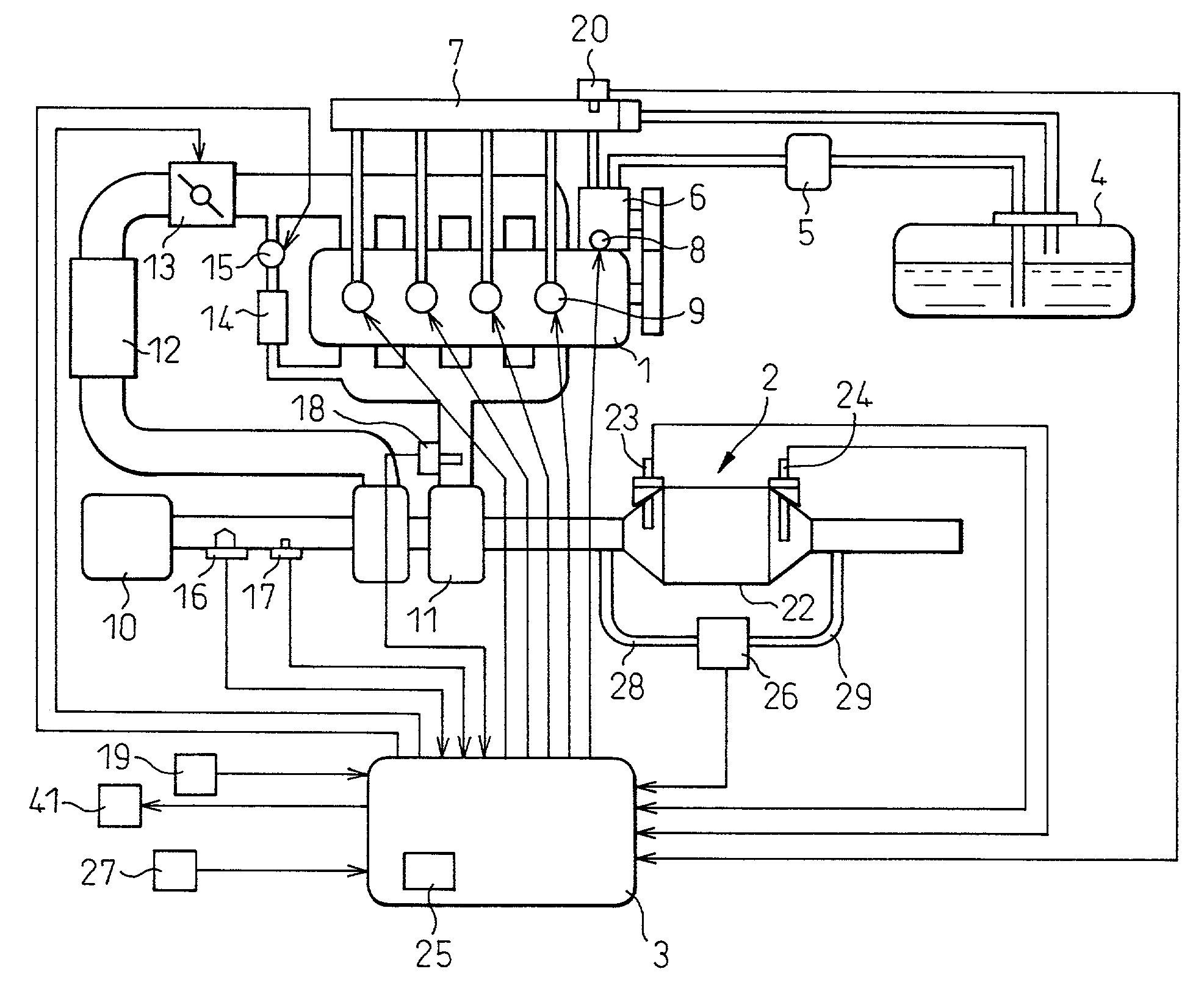
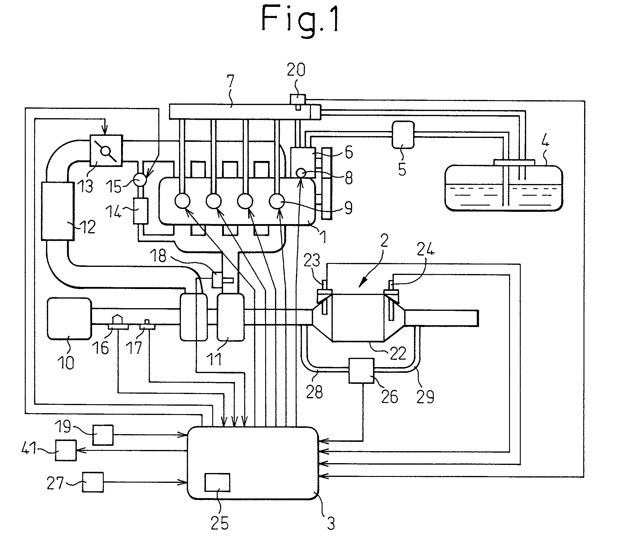
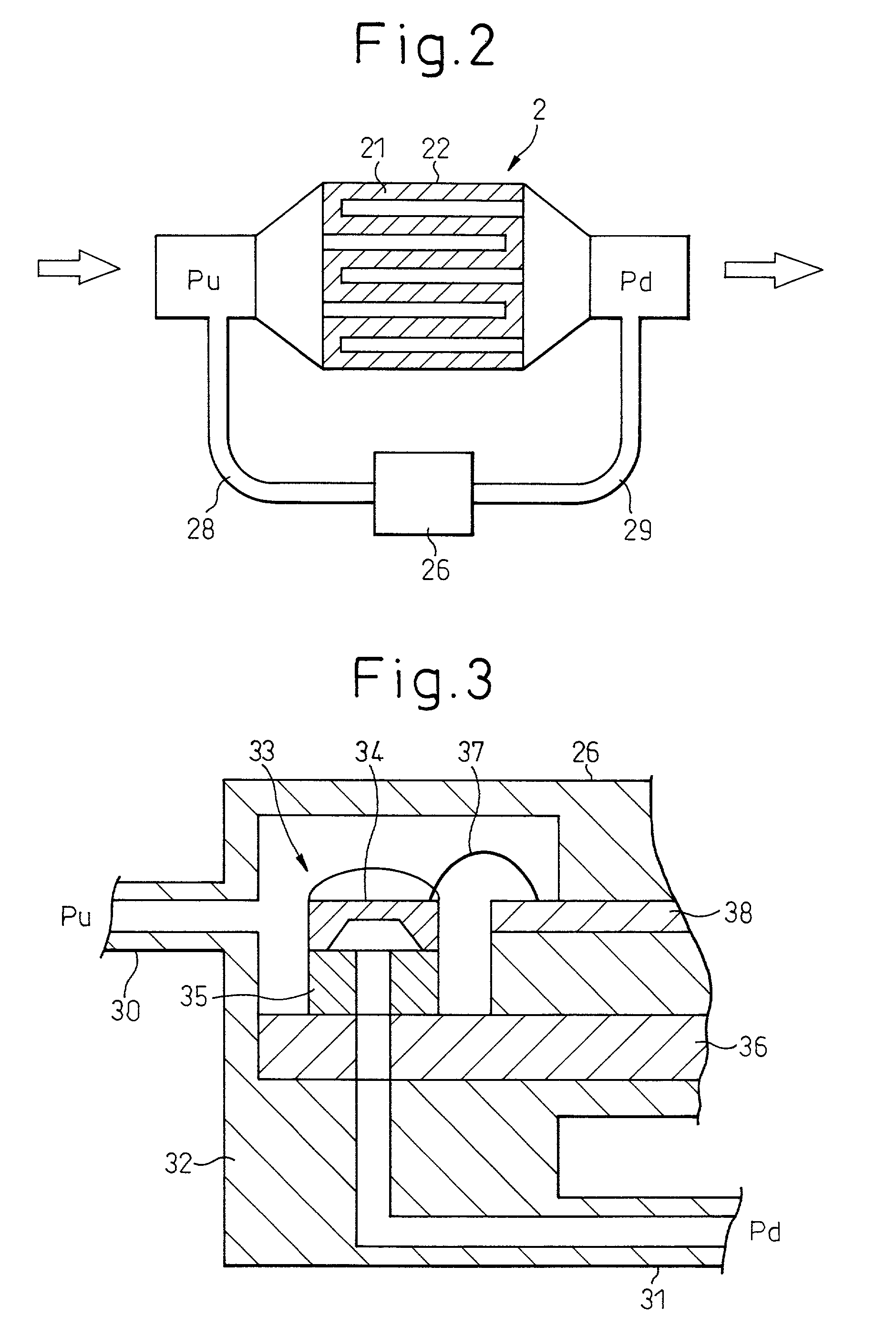
[0085] As described above, the apparent passage area (A) of the DPF 2, that is decreased due to the deposition of the PM on the DPF 21, is detected, and the DPF 21 is regenerated without being unnecessarily heated. Therefore, the DPF 21 is reliably regenerated irrespective of the state where the PM is deposited, requiring a minimum of regenerating time, and the consumption of fuel can be saved. In regenerating the DPF 21, further, the regeneration is executed for a minimum period of time to minimize the consumption of fuel used for the regeneration processing. It is therefore possible to precisely detect the passage area of the exhaust gas passage that is recovered due to the regeneration.

[0086] This embodiment provides a method of finding the apparent passage area (A) of the DPF 21 maintaining a sufficient degree of precision, making it possible to precisely detect an abnormal increase in the passage area caused by breakage. Therefore, the state where the DPF 2 is broken and the P...


PUM

PropertyMeasurementUnit
Temperatureaaaaaaaaaa
Pressureaaaaaaaaaa
Flow rateaaaaaaaaaa

Abstract

The permeability of a DPF 21 mounted on a diesel engine 1 is evaluated by calculating the apparent passage area (A) based upon a difference in the pressure between the upstream and the downstream sides of the DPF 21 and upon other engine data, an alarm is given to a driver based on the results of evaluation, and the operation mode is changed over to regenerate the DPF 21. An abnormal increase in the passage area caused by breakage is accurately detected, and it does not happen that the PM is released into the open air for extended periods of time due to the breakage of the DPF 21. Further, without the need of dismantling the DPF 21, the DPF 21 can be reliably burned and regenerated without being undesirably overheated in every operation mode of the engine 1.

Description

[0001] 1. Field of the Invention[0002] The present invention relates to a device for purifying the exhaust gas of an automotive engine. More particularly, the invention relates to a device for purifying exhaust gas of an engine in which a permeability of a particulate filter mounted on a diesel engine is evaluated by calculating the apparent passage area based upon a difference in the pressure between the upstream and the downstream sides of the particulate filter and upon other engine data, an alarm is given to a driver based on the results of evaluation, and the particulate filter is properly regenerated.[0003] 2. Description of the Related Art[0004] In order to prevent air pollution, there has heretofore been widely used a particulate filter for trapping particulate matter emitted from automotive engines and, particularly, from diesel engines. Particulate filters of a variety of types have been proposed. Among them, the particulate filter of the type which automatically burns the...

Claims


Application Information

Patent Timeline
IPC IPC(8): F02D45/00B01D46/42F01N3/02F01N3/24F01N9/00F01N11/00F02D41/02F02D41/04F02D41/06F02D41/14F02D41/24F02D41/38F02D41/40
CPCF01N9/002Y02T10/47F01N11/002F01N2550/04F02D41/027F02D41/062F02D41/1441F02D41/1446F02D41/1448F02D41/1454F02D41/187F02D41/2422F02D41/3809F02D41/405F02D2041/228F02D2200/0404F02D2200/0406F02D2200/0414F02D2200/0602F02D2200/1004F02D2200/703F02D2250/18Y02T10/44F01N11/00Y02T10/40
Inventor KINUGAWA, MASUMISEKIGUCHI, KIYONORIFUJITA, TATSUYA
Owner DENSO CORP
Learn More