Digital radio frequency tag

a digital radio frequency tag and radio frequency technology, applied in the field of communication systems, can solve the problems of unattractive target applications for rf tags, data rates associated with the use of drfm, and considerable constraints imposed by drfm technique on the amount of data that can be transmitted

Inactive Publication Date: 2002-12-26
RAYTHEON CO
View PDF0 Cites 33 Cited by
  • Summary
  • Abstract
  • Description
  • Claims
  • Application Information

AI Technical Summary

Problems solved by technology

Unfortunately, there many shortcomings associated with conventional RF tags.
Firstly, the DRFM technique imposes a considerable constraint on the amount of data that can be transmitted.
Secondly, there is little that can be done with a DRFM and, inasmuch as the tag is typically limited to a few bits of information, the data rates associated with the use of a DRFM are typically extremely low.
The combination of higher energy levels and higher observeability of the reply signal renders this approach unattractive for the target application for RF tags.
In addition, he higher power levels further limit battery life.
Thirdly, conventional RF tag designed is limited with respect to the types of radar signals that may be answered.
Finally, inasmuch as conventional RF tags transmit and receive data using simple analog modem techniques, these devices are susceptible to interference and dropouts.

Method used


Image

  • Digital radio frequency tag
  • Digital radio frequency tag
  • Digital radio frequency tag

Examples


Embodiment Construction

[0024] Illustrative embodiments and exemplary applications will now be described with reference to the accompanying drawings to disclose the advantageous teachings of the present invention.

[0025] While the present invention is described herein with reference to illustrative embodiments for particular applications, it should be understood that the invention is not limited thereto. Those having ordinary skill in the art and access to the teachings provided herein will recognize additional modifications, applications, and embodiments within the scope thereof and additional fields in which the present invention would be of significant utility.

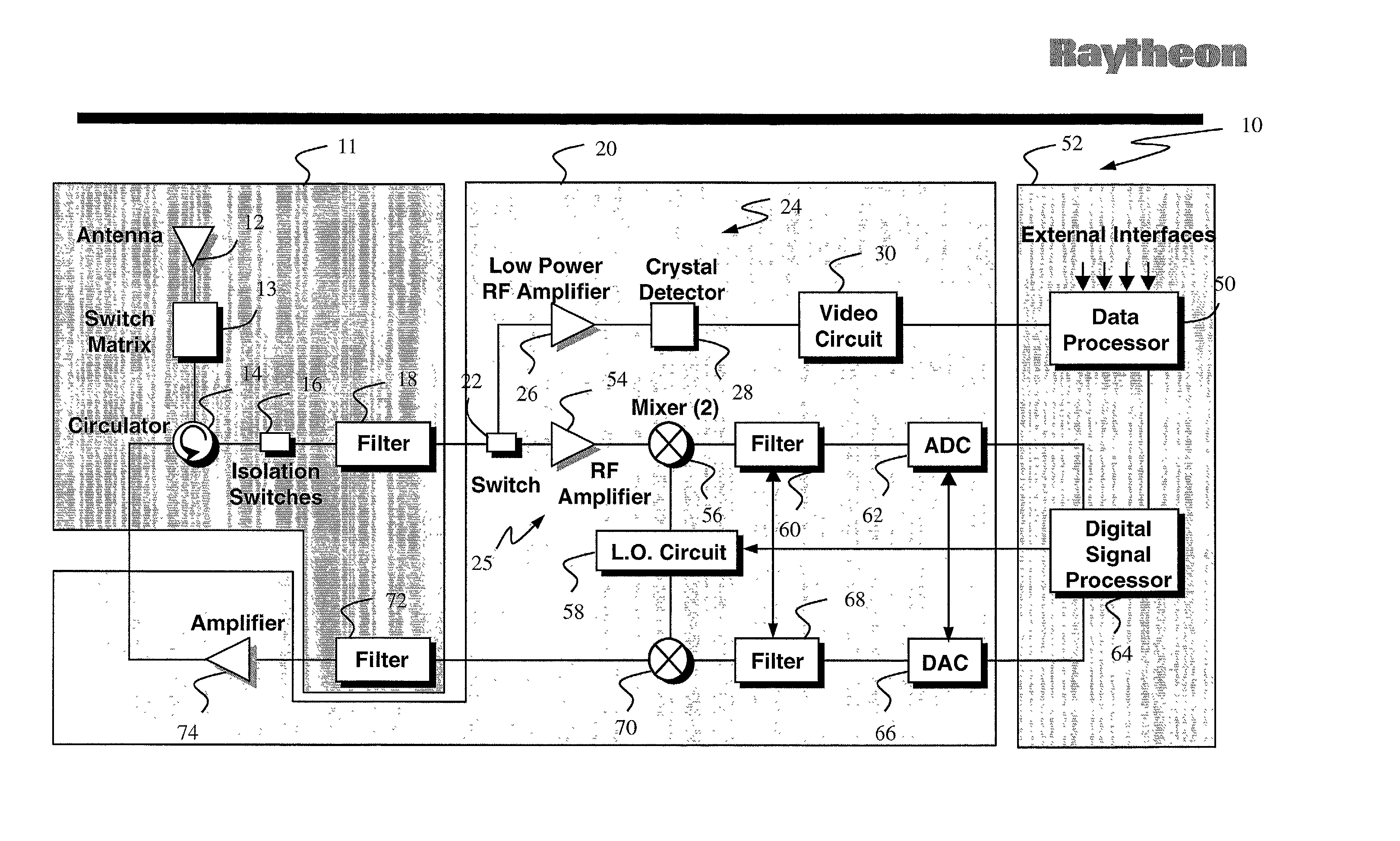
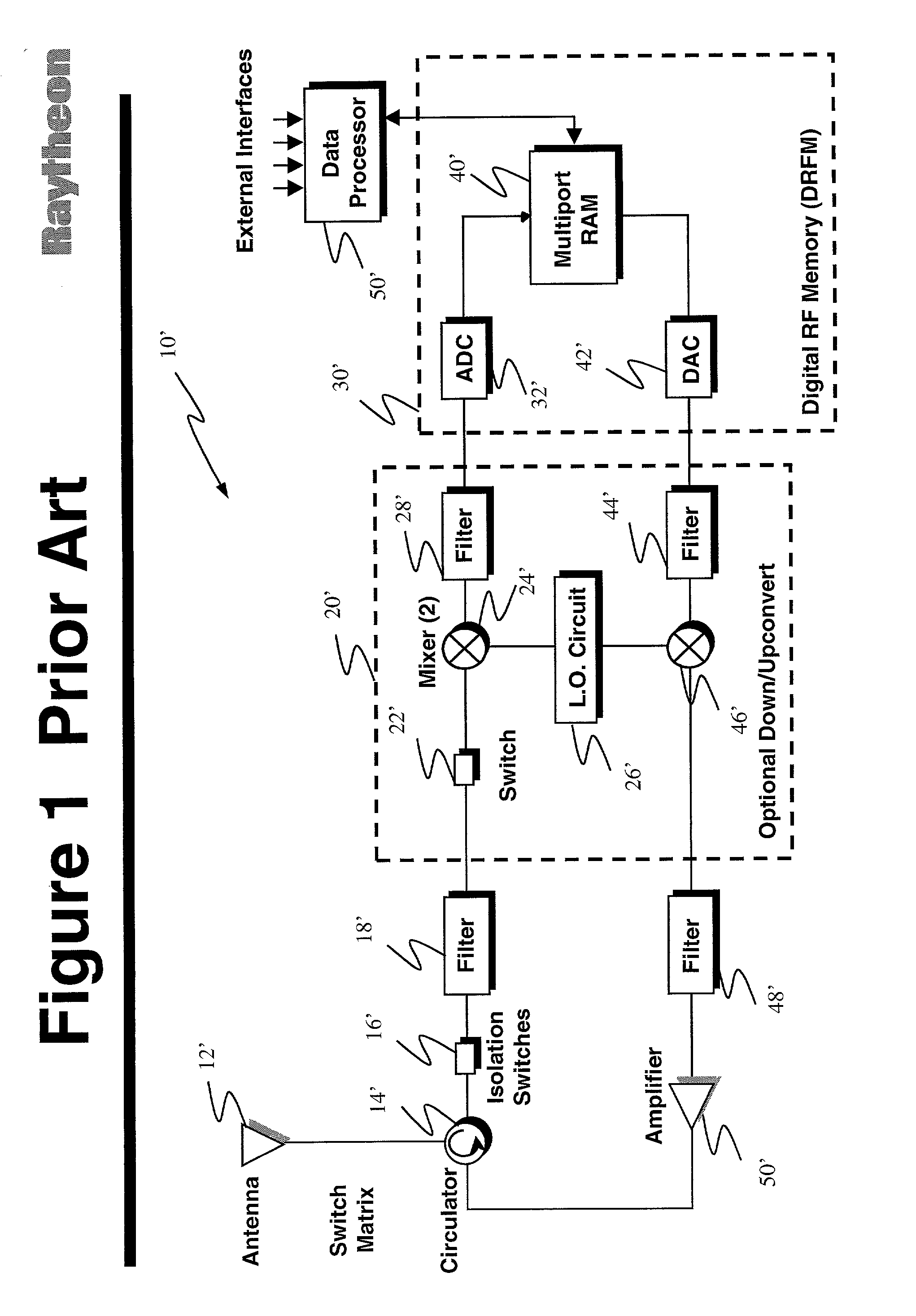
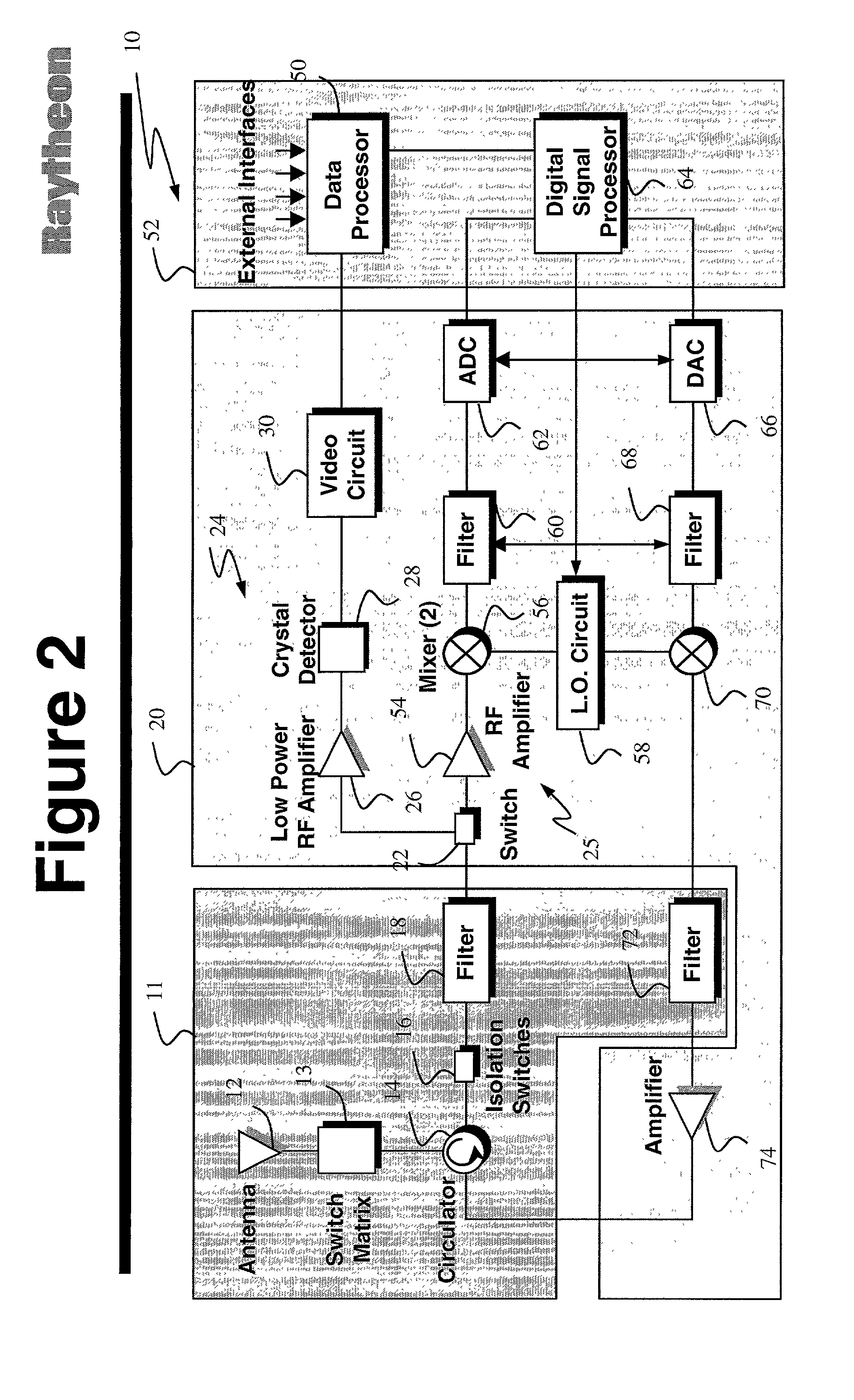
[0026] FIG. 1 is a block diagram of an RF tag implemented in accordance with conventional teachings. The typical conventional tag 10' includes an RF antenna 12' which feeds a circulator 14'. The circulator 14' effects communication of received radar pulses to a filter 18' via an isolation switch 16'. The filtered signal is fed to a mixer 24' in an ...


PUM


Abstract

A digital RF tag (10) for providing an automatic reply to an electromagnetic signal. The system includes a radar receiver (11, 20); signal and data processors (50, 64) for analyzing the electromagnetic signal to extract data with respect thereto and for synthesizing a second electromagnetic signal; and a radar transmitter (11, 20). The radar receiver (11, 20) is a narrow band radar receiver. The use of a narrow band receiver minimizes power consumption and extends battery life. The inventive RF tag (10) tracks the received radar signal. The data processor (50) includes a microprocessor adapted to execute software designed to implement the tracking function. While the received radar signal is being tracked, type and timing data are extracted and used to synthesize a reply signal. The use of a synthesized reply signal, as opposed to a recorded and modified transmit signal as a reply signal, allows for the transmission of the cleaner (noise free) reply signal. In addition, other data including voice and video may be impressed onto the reply signal.

Description

[0002] 1. Field of the Invention[0003] The present invention relates to communication systems. More specifically, the present invention relates to radio frequency tags.[0004] 2. Description of the Related Art[0005] Radio frequency (RF) tags are well-known in the art. RF tags are small electronic devices that receipt and recognize radar signals of a particular type and generate and transmit a reply in response thereto. When received by the transmitting radar, the reply is decoded to ascertain the identity and location of the RF tag.[0006] Conventional RF tags were simple repeaters designed to receive and report synthetic aperture radar (SAR) signals, shift the signal in Doppler, and transmit a reply with respect theretousing a technique known as "digital radio frequency memory" (DRFM). These devices also typically perform simple modifications of the received signal, to send additional useful information.[0007] One typical application for RF tags is to enable ground forces to communic...

Claims


Application Information

Patent Timeline
Patent Type & Authority Applications(United States)
IPC IPC(8): G01S13/76
CPCG01S13/767
Inventor BEARD, JAMES K.
Owner RAYTHEON CO
Why Eureka
Try Eureka