Gear shift apparatus for manual transmission

Inactive Publication Date: 2003-01-02
HONDA MOTOR CO LTD
View PDF8 Cites 10 Cited by
  • Summary
  • Abstract
  • Description
  • Claims
  • Application Information

AI Technical Summary

Benefits of technology

[0013] The present invention has been made to solve the foregoing problem, and it is an object of the invention to provide a gear shift apparatus for a manual transmission which utilizes an actuator to prevent a miss shift manipulation from a forward gear stage to a reverse gear stage, wherein the gear shift apparatus allows a driver to perform a selecting manipulation with a small force for forcedly releasing a miss shift preventing state and therefore have a light gear shift feeling.
[0017] According to this gear shift apparatus for a manual transmission, the restraint cam is held at the permitting position by an urging force of the urging means when the actuator is inoperative, permitting the select cam to pivotally move to the reverse direction, so that the transmission can be shifted to the reverse transmission gear stage. On the other hand, as the actuator is driven, the restraint cam is pressed by the moving element from the permitting position to the prohibiting position against an urging force of the urging means, thereby prohibiting the select cam from pivotally moving to the reverse position. As a result, the driver is prohibited from performing a manipulation for selecting the reverse select position, to prevent an erroneous shift to the reverse transmission gear stage.
[0018] When the driver performs a manipulation for selecting a forward select position for selecting a forward transmission gear stage in the miss shift preventing state in which the restraint cam is held at the prohibiting position, the prohibition releasing means of the select cam responsively presses the restraint cam into a pivotal movement from the prohibiting position to the permitting position. Thus, the moving element can be moved from the prohibiting position to the permitting position together with the restraint cam against a driving force of the actuator. Therefore, even if a shift to the reverse transmission gear stage is erroneously disabled due to the actuator which is stuck when the restraint cam remains at the prohibiting position, such a situation can be released by force. In this event, since two cams are used, the gear shift disabled state can be forcedly released in an efficient manner through the transmission of a torque from the pivotally moved select cam to the restraint cam, as compared with the conventional release operation which relies on the transmission of a horizontal force as a vertical force through a cam face. Consequently, the miss shift preventing state or gear shift disabled state can be released with a much lighter force than before.
[0020] According to this preferred embodiment of the gear shift apparatus for a manual transmission, since the distance between the center of pivotal movement of the restraint cam and a location of the select cam pressed to the prohibition releasing means is set to be longer than the distance between the center of pivotal movement of the restraint cam and a location of the restraint cam contacted to the moving element, the restraint cam can be driven with a smaller torque of the select cam in accordance with the principles of lever during a selecting manipulation. As a result, the miss shift preventing state or erroneous gear shift disabled state can be released with a yet smaller force than before, permitting the driver to have a lighter gear shift feeling.

Problems solved by technology

Thus, due to an extremely small vertical component force relative to the horizontal force acting on the pin 84 from the cam face 83a, a large force is required for manipulating the transmission lever for selection, when the gear shift preventing state is forcedly released, resulting in a problem that the driver has a bad manipulation feeling.

Method used


Image

  • Gear shift apparatus for manual transmission
  • Gear shift apparatus for manual transmission
  • Gear shift apparatus for manual transmission

Examples


Embodiment Construction

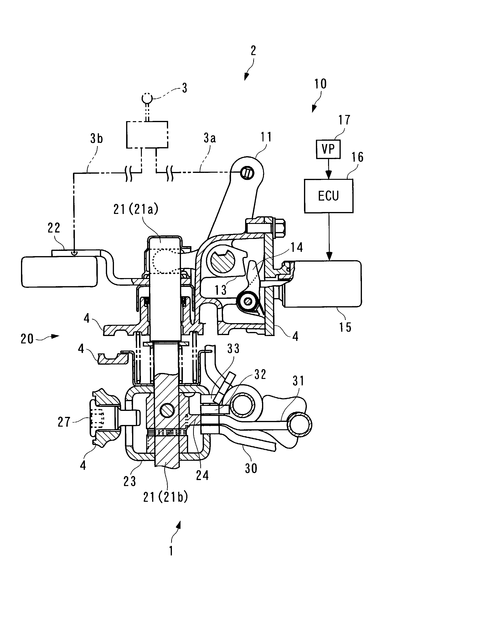
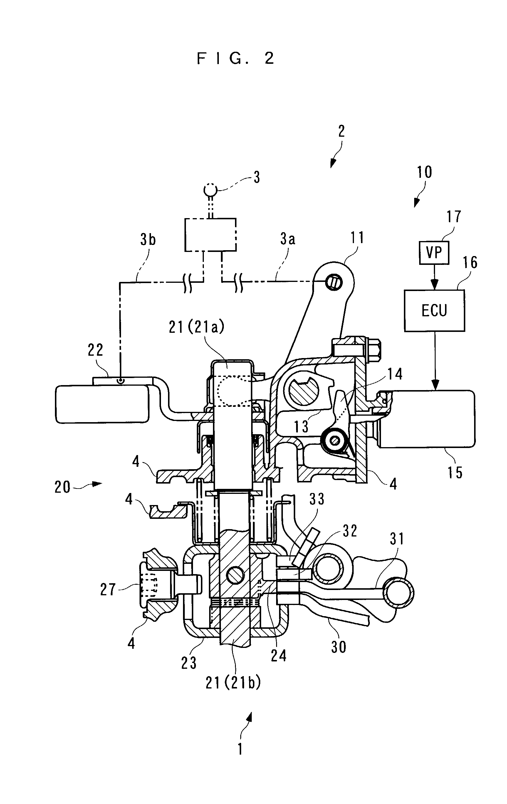
[0034] In the following, a gear shift apparatus for a manual transmission according to one embodiment of the present invention will be described with reference to the accompanying drawings. FIG. 2 generally illustrates the configuration of a gear shift apparatus according to one embodiment, and a manual transmission to which the gear shift apparatus is applied. Assume, in the following description, that the near side and far side in FIG. 2 are called the front side and rear side, respectively, and the left side and right side in the figure are called the left side and right side, respectively.

[0035] The illustrated manual transmission 2, which is equipped in a vehicle, not shown, comprises a transmission lever 3; a case 4 made up of a clutch case, a transmission case, and the like which are integrated into a single assembly; a gear shift apparatus 1 mounted to the case 4; a transmission gear train (not shown) contained in the case 4; and the like.

[0036] The manual transmission 2 is ...


PUM


Abstract

A gear shift apparatus for a manual transmission utilizes an actuator to prevent a miss shift manipulation from a forward gear stage to a reverse gear stage. The gear shift apparatus permits the driver to forcedly release a miss shift preventing state with a smaller force. In the gear shift apparatus for a manual transmission, a select cam is responsive to a selecting manipulation to pivotally move to forward positions corresponding to forward select positions and a reverse position corresponding to a reverse select position. A restraint cam is driven to a prohibiting position by a plunger when a solenoid is energized to prohibit the select cam from pivotally moving to the reverse position. In this prohibiting state, as the select cam is pivotally moved toward a forward position in response to a manipulation for selecting a forward select position, a release protrusion of the select cam presses the restraint cam to pivotally move the same from the prohibiting state to a permitting position.

Description

[0001] 1. Field of the Invention[0002] The present invention relates generally to a gear shift apparatus for a manual transmission for use in a vehicle such as an automotive vehicle, and more particularly, to a gear shift apparatus for a manual transmission which comprises a miss shift preventing mechanism for preventing a driver from erroneously operating the transmission from a forward gear stage to a reverse gear stage during forward running of the vehicle.[0003] 2. Description of the Prior Art[0004] Conventionally, as a gear shift apparatus of the type mentioned above, one illustrated in FIGS. 1A-1D is known. This manual transmission has a shift pattern (for example, see FIG. 3) in which forward first through sixth gear stage positions are disposed at respective ends of three parallel lines, and an additional reverse gear stage position defined outside the fifth or sixth gear stage position in a select direction indicated in FIG. 3. The gear shift apparatus 80 also comprises an ...

Claims


Application Information

Patent Timeline
IPC IPC(8): F16H63/36F16H61/18F16H61/24F16H63/30F16H63/34
CPCF16H61/18F16H61/24F16H63/302F16H63/3408Y10T74/20104Y10T74/20116Y10T74/20098Y10T74/20091F16H2061/185
Inventor OKUBO, KIYOKAZUYAKOU, TAKAYUKIONUMA, YASUSHINEMOTO, KEIJIHOSODA, KAZUFUMI
Owner HONDA MOTOR CO LTD
Why Eureka
Try Eureka