Pattern correction method, apparatus, and program
a technology of opc processing and apparatus, applied in the field of opc processing, can solve the problems of poor correction accuracy, large time required for opc processing of graphics processing and distance calculation, and the prevention of reducing yield
- Summary
- Abstract
- Description
- Claims
- Application Information
AI Technical Summary
Problems solved by technology
Method used
Image
Examples
first embodiment
[0030] (First Embodiment)
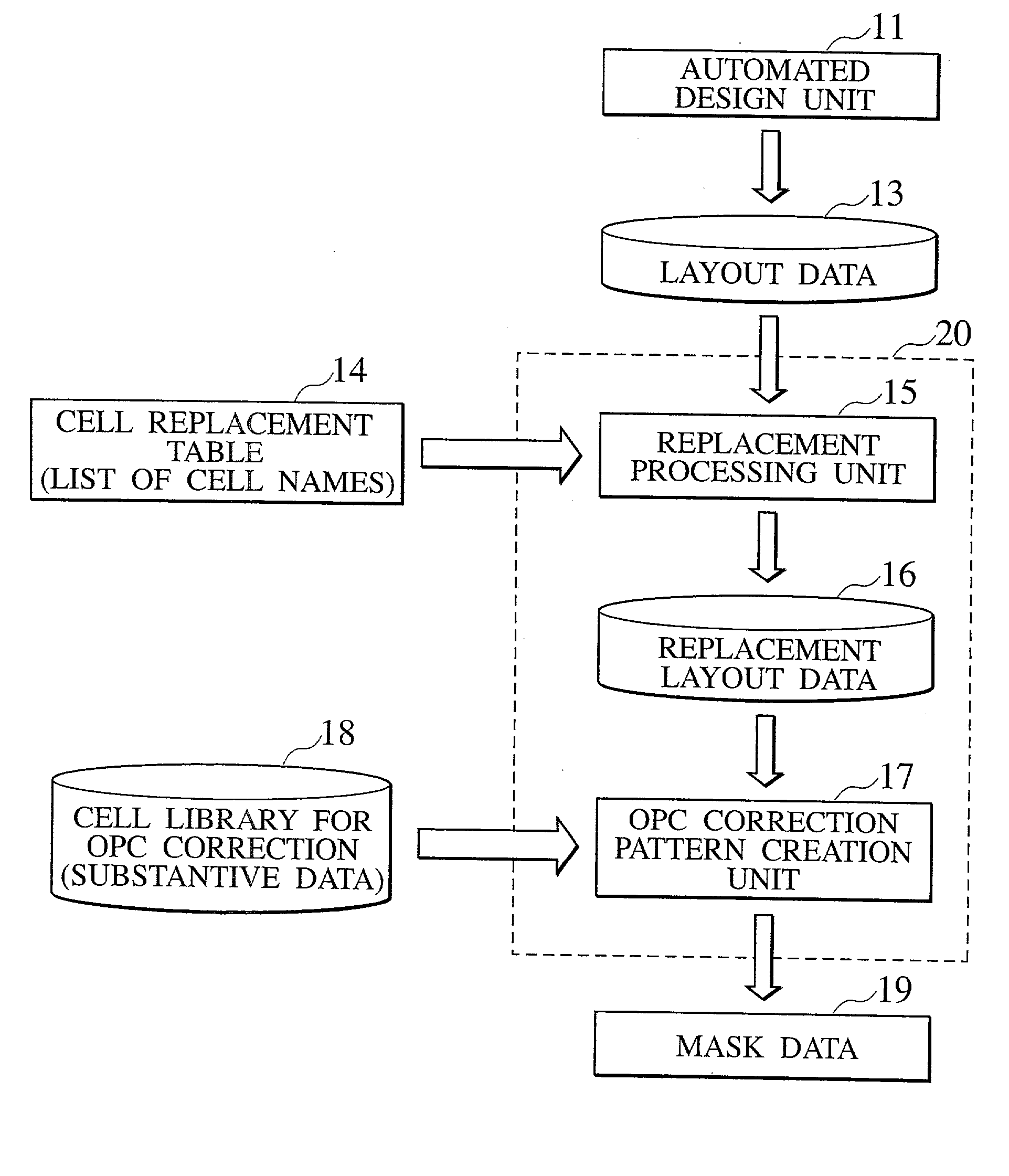
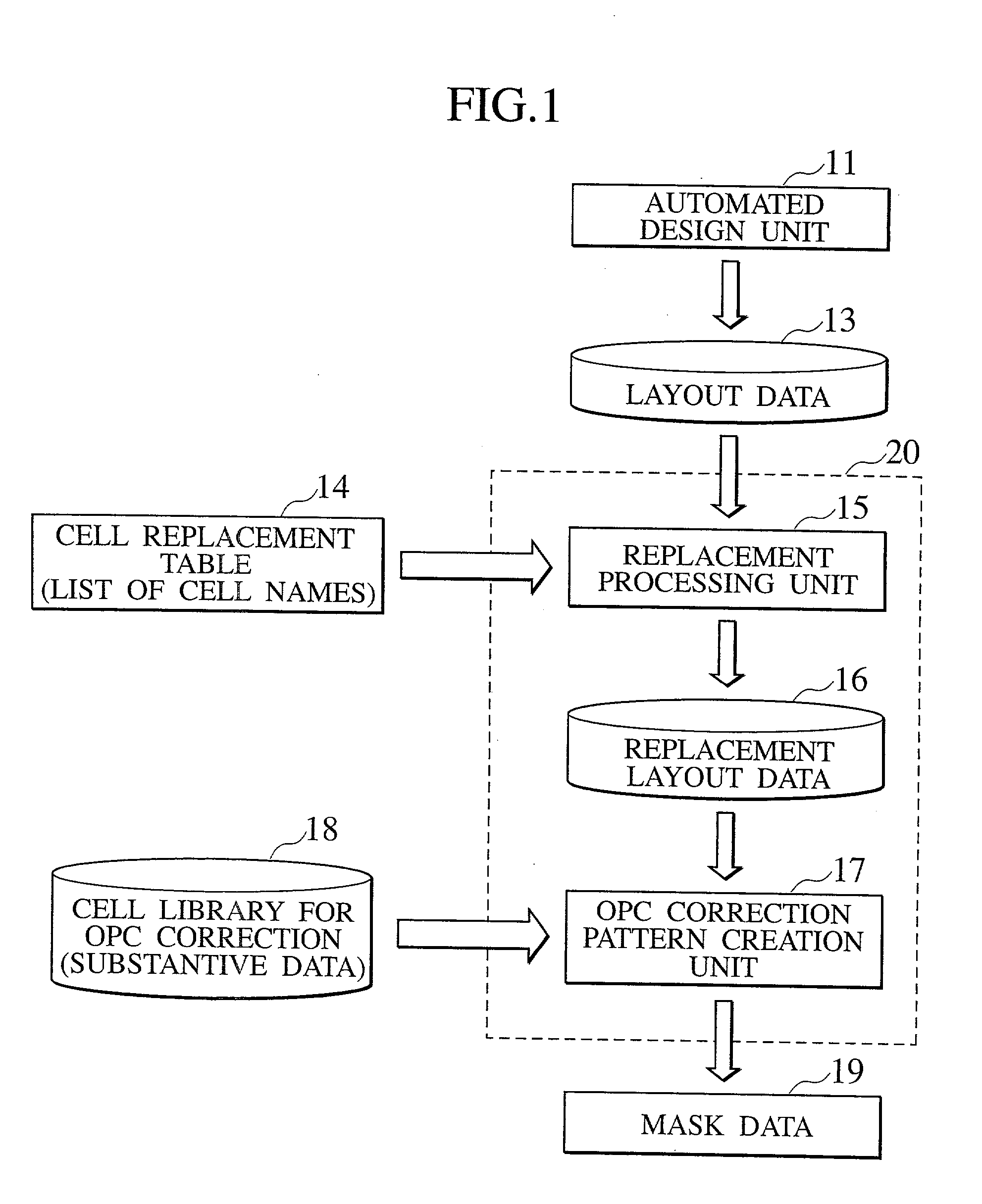
[0031] FIG. 1 illustrates an outline of optical proximity correction (OPC) according to the first embodiment of the present invention. OPC is initiated by entering layout data 13 created by an automated design unit 11, such as CAD, into an OPC correction processing unit 20. The OPC correction processing unit 20 applies pattern correction to layout data 13, such as an interconnect pattern designed with CAD, in anticipation of the optical proximate effect caused by the exposure a micro pattern.
[0032] During this pattern correction, the input design layout data 13 is converted to replacement layout data 16 by a replacement processing unit 15 while referencing a cell replacement table 14. The replacement layout data is transmitted to an OPC correction pattern creation unit 17. Referencing a cell library 18 for OPC correction, the OPC correction pattern creation unit 17 imports a substantive post-correction pattern and outputs mask data 19.
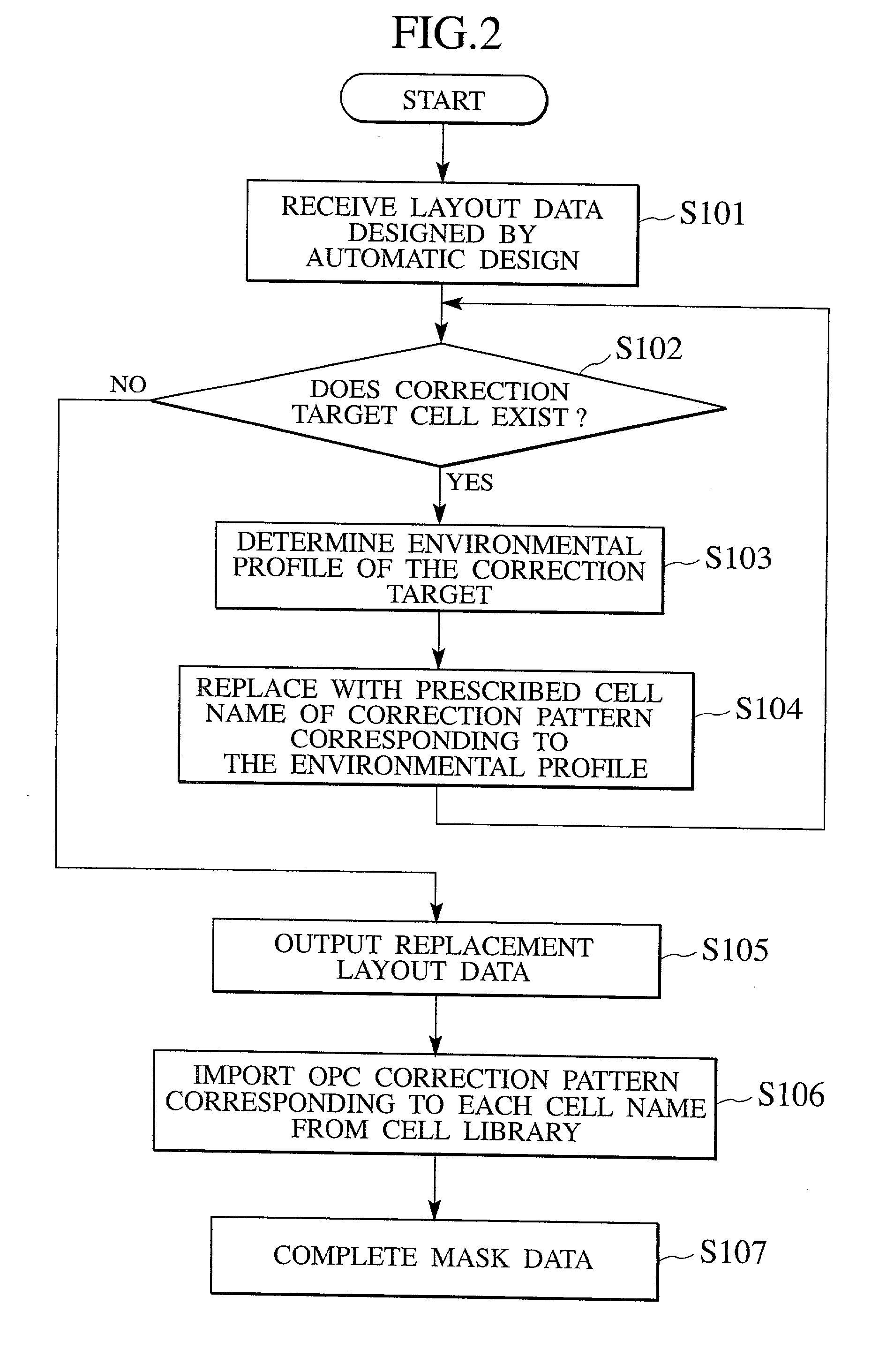
[0033] FIG. 2 is a more...
second embodiment
[0062] (Second Embodiment)
[0063] In the first embodiment, the correction of multi-level interconnect patterns in the rectangular coordinate system was described. In the second embodiment, pattern correction for diagonal interconnect is described while referencing FIGS. 11 to 13.
[0064] The case where the lower-level metal interconnect extends toward the prescribed direction (e.g., horizontal direction) on the rectangular coordinate system and the upper-level metal interconnect at the upper level extends toward diagonal direction at the prescribed angle with the lower-level horizontal interconnect is considered.
[0065] FIG. 11 illustrates segments for determining the environmental profile for the upper-level metal interconnect 121, which constructs the VIA cells, and FIG. 12 illustrates segments for determining the environmental profile for the lower-level metal interconnect 123. In the second embodiment, the cross-sectional shape of VIA contacts 122, which connect the upper-level diag...
third embodiment
[0072] (Third Embodiment)
[0073] FIG. 14 is a diagram of an OPC pattern correction apparatus according to a third embodiment of the present invention. The pattern correction apparatus 150 comprises a CPU (correction processing unit) 151; memory 152; and an input / output unit 153. A design pattern designed with an automated layout unit, such as CAD, is input to the pattern correction apparatus 150 via the input / output unit 153.
[0074] The memory 152 stores a cell replacement table 157 and a cell library 158 for OPC correction. The cell replacement table 157 indexes all possible environmental profiles with the names (referred to as cell names) representing the most appropriate correction shape corresponding to each environmental profile in relation to the pattern (target cell) to be corrected and stores them. The cell library 158 for OPC correction stores the actual correction pattern data indicated by the cell names in the cell replacement table 157.
[0075] The CPU 151 comprises an envir...
PUM
| Property | Measurement | Unit |
|---|---|---|
| optical proximity correction | aaaaa | aaaaa |
| width | aaaaa | aaaaa |
| VIA resistance | aaaaa | aaaaa |
Abstract
Description
Claims
Application Information
 - R&D
- Intellectual Property
- Life Sciences
- Materials
- Tech Scout
- Unparalleled Data Quality
- Higher Quality Content
- 60% Fewer Hallucinations
Browse by: Latest US Patents, China's latest patents, Technical Efficacy Thesaurus, Application Domain, Technology Topic, Popular Technical Reports.
© 2025 PatSnap. All rights reserved.Legal|Privacy policy|Modern Slavery Act Transparency Statement|Sitemap|About US| Contact US: help@patsnap.com


