Chimney vacuum system

a vacuum system and chimney technology, applied in the field of chimneys, can solve the problems of inability to effectively use vacuum heads and the like in and around the flue mechanism of various kinds, and the system is often quite cumbersome to opera

Inactive Publication Date: 2003-01-09
KELLER THOMAS J
View PDF0 Cites 9 Cited by
  • Summary
  • Abstract
  • Description
  • Claims
  • Application Information

AI Technical Summary

Problems solved by technology

As one might expect, these systems where often quite cumbersome to operate, and often include fixed mechanical attachments for limited use to clean up residual debris in difficult to reach areas.
Later developments by Evans (U.S. Pat. No. 4,807.590) and Broussard (US sought to provide a vacuum system as a portable device, but were met with mechanical limitations which inhibit the effective use of vacuum heads and the like in and around flue mechanisms of various sorts.

Method used


Image

  • Chimney vacuum system
  • Chimney vacuum system
  • Chimney vacuum system

Examples


Embodiment Construction

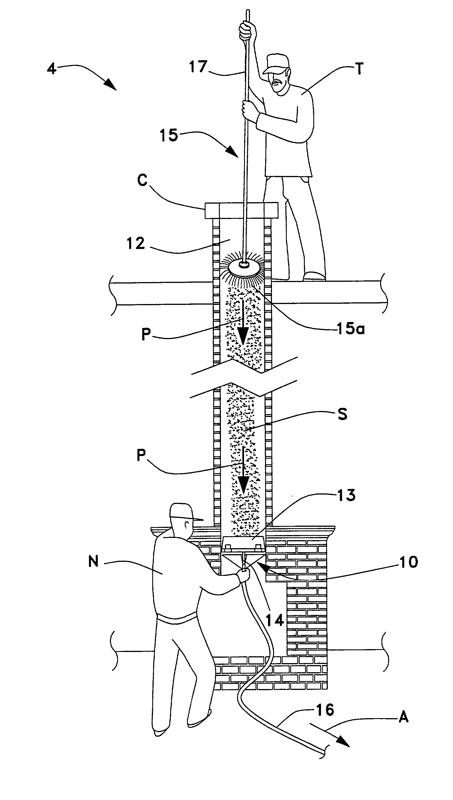
[0020] The present invention is directed to a chimney vacuum adapter and system for cleaning accumulated soot S from the flue of chimneys C. The preferred embodiment of the invention is depicted in FIGS. 1-3, and is generally referenced by numeral 4. The chimney adapter feature of the system 4 is generally referenced by numeral 10.

[0021] As best seen in FIG. 1, the chimney vacuum system 4 is shown to illustrate the removal of accumulated soot S from a flue 12. The chimney adapter 10 is shown adapted to a flue mechanism 13 via a flue handle 14 at one end, and attached to an effluent hose 16 for soot or waste removal at another end via a frictional fit. This particular attachment provides a mechanical and fluid seal from the attachment point of the adapter head 10 with the flue mechanism 13 (via flue handle 14), and from the hose 16 fastened to the adapter 10 at another end to transport soot S under a vacuum to a remote refuse container (not shown). The refuse container for the chimne...


PUM


Abstract

A chimney vacuum system having an adapter head for fluidly removing accumulated soot under vacuum pressure from a flue or chimney. The chimney vacuum system includes a hose adapted to the head via a frictional fit. The adapter head of the chimney system has a body portion which narrows in volume from an outer diameter to an inner diameter. Extending from the inner diameter is a neck portion for attaching an effluent hose and refuse container downstream. The body of the adapter head includes a sealing gasket defined therein for providing a mechanical and fluid seal with a flue mechanism element in the flow path of the flue.

Description

[0001] 1. Field of the Invention[0002] The present invention relates generally to chimneys. More specifically, the invention is a funnel attachment for a chimney, sweep vacuum which removes soot from a fireplace flue or work space without the need for tarps and the like to catch excavated soot spillage.[0003] 2. Description of the Related Art[0004] The general use of particle removing apparatuses have been in existence as early as 1920. It was A. E. Burges (U.S. Pat No. 1,371,468) who was credited with the idea of harvesting or removing cotton in its natural state by a suction based apparatus. This principle took root in the minds of others such as E. Gray (U.S. Pat. No. 1,465,711) and Engstrom (U.S. Pat. No. 1,979,873) which utilized suction channels for removing soot from furnaces in 1922 and 1933, respectively. As one might expect, these systems where often quite cumbersome to operate, and often include fixed mechanical attachments for limited use to clean up residual debris in d...

Claims


Application Information

Patent Timeline
Patent Type & Authority Applications(United States)
IPC IPC(8): A47L7/00A47L9/02B08B9/02B08B9/04B08B15/00
CPCA47L7/0071A47L7/009A47L9/02B08B9/027B08B9/035B08B9/0436B08B15/00
Inventor KELLER, THOMAS J.
Owner KELLER THOMAS J
Why Eureka
Try Eureka