
Display apparatus and method particularly useful in simulators

a technology of display apparatus and simulator, which is applied in the field of display methods and equipment particularly useful in simulators, can solve the problems of affecting the viewing experience of viewers, affecting the quality of the background image, and reducing so as to reduce the resolution of the target image and increase the cost of increasing the background image resolution. , the effect of high resolution

Inactive Publication Date: 2003-01-16
COMVIEW VISUAL SYST
View PDF0 Cites 10 Cited by
  • Summary
  • Abstract
  • Description
  • Claims
  • Application Information

AI Technical Summary

Benefits of technology

[0007] The background image video stream need not be updated at all, and may be separated from a stills picture, for example. Preferably, the data update-rate is 0-1 Hz for the background image video stream and 15-60 Hz for the target image video stream. Such a method enables a substantial reduction in the number of image generators and even the elimination of an image generator for the background image which can be pre-rendered as indicated above.
[0014] As will be described more particularly below, such apparatus and method avoid the transition problem between a high resolution target image and a low resolution background image heretofore involved in the prior art, since it enables both the target image and the background image to be of the same resolution, without lowering the resolution of the target image or inordinately increasing the costs for increasing the resolution of the background image. These advantages are particularly important in simulators as they enable simulators of relatively high resolution to be constructed at relatively low cost.

Problems solved by technology

Using two projectors, one for the low resolution background image and the other for the high resolution target image, may produce geometrical or color non-uniformities, or seams, between the two images, which would be disturbing to the viewer.
A visually acceptable transition could, of course, also be produced by matching the resolutions of the target image and background image, but this would involve either losing the benefits of the high resolution of the target image if its resolution is to be reduced to match that of the background image, or substantially increasing the costs if the resolution of the background image is to be increased to match that of the target image.

Method used


Image

  • Display apparatus and method particularly useful in simulators
  • Display apparatus and method particularly useful in simulators
  • Display apparatus and method particularly useful in simulators

Examples


Embodiment Construction

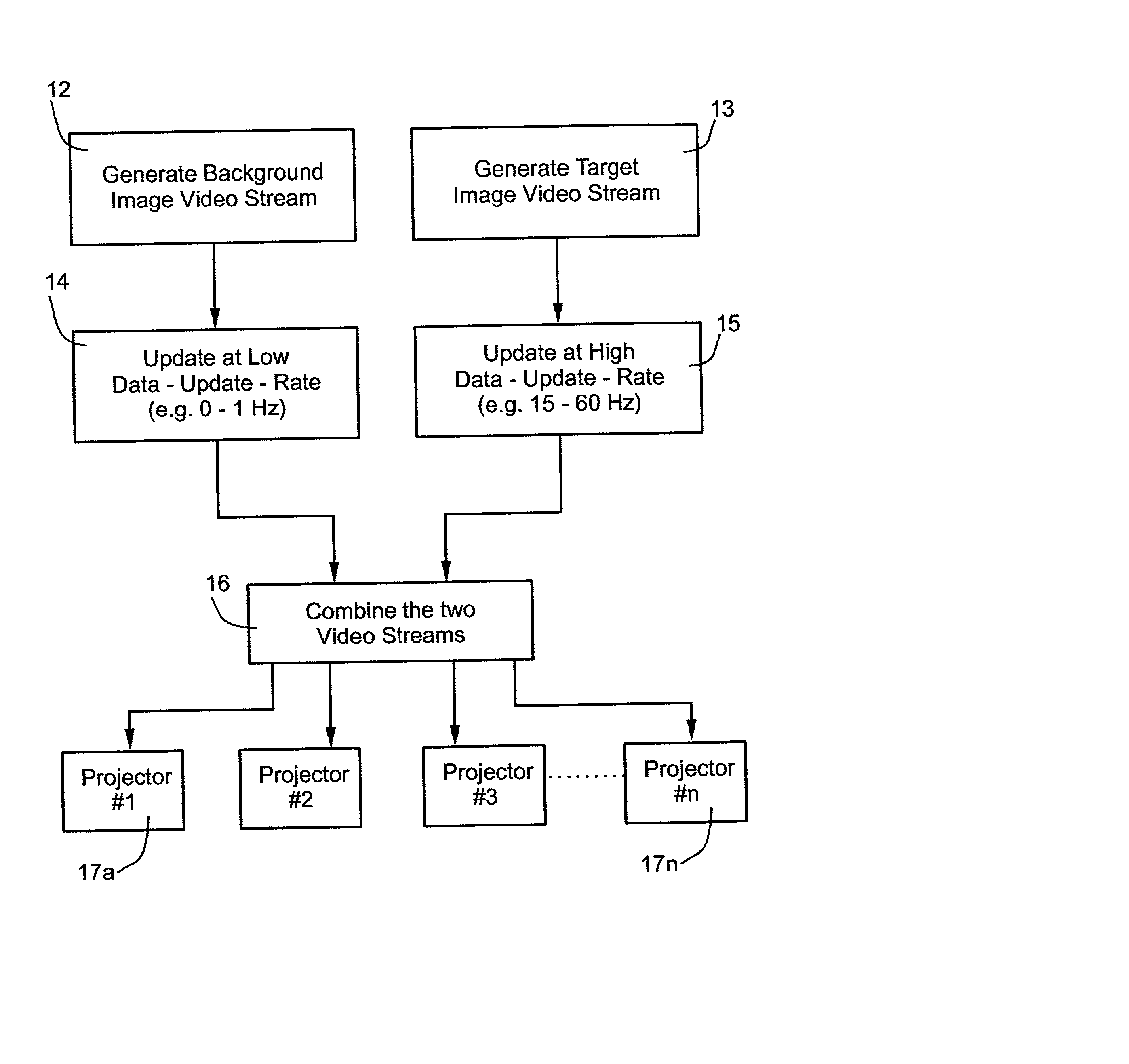
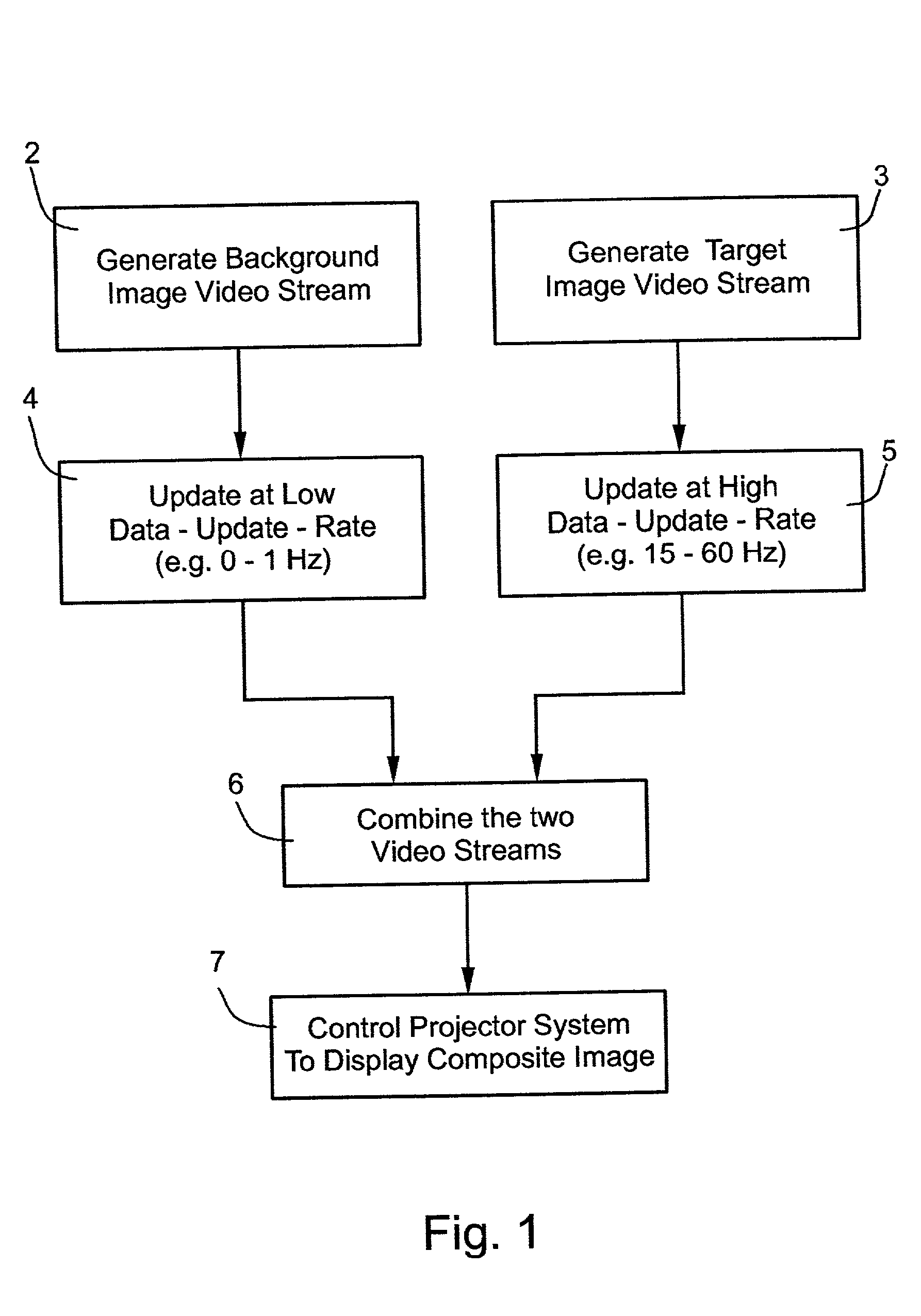
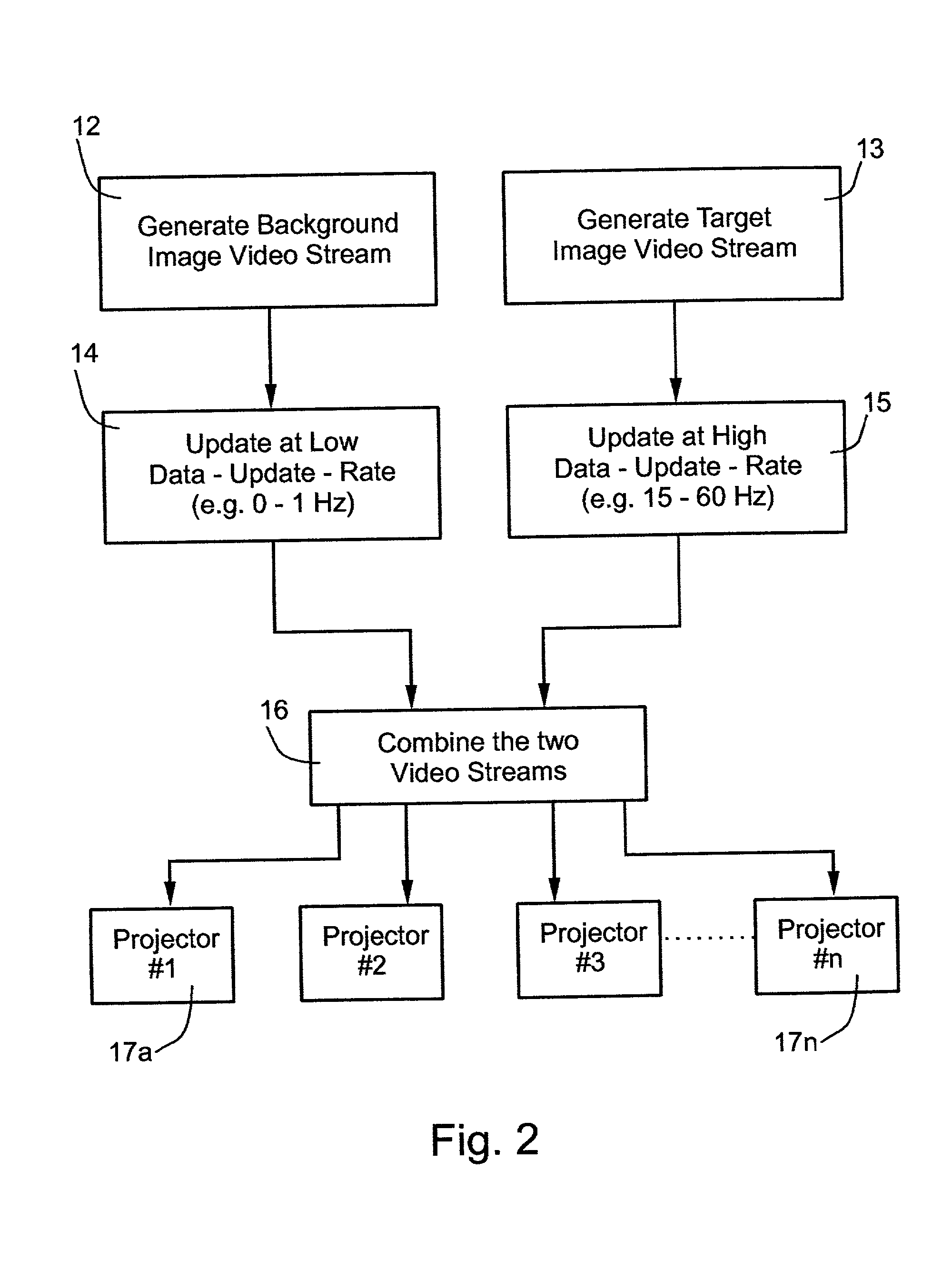
[0021] FIG. 1 is a simplified flow chart illustrating a method of displaying composite images in accordance with the present invention. The composite images displayed are those as viewed from a relatively stationary eye point, so as to include a moving target image of relatively small field-of-view overlaid on a background image of relatively large field-of-view. For example, in an air controller system, the moving target images would be aircraft, and the background image would be the environment (e.g., terrain, cloud formation, etc.) in which the aircraft travels. In a land vehicle control system (e.g., trucks, buses, etc.), the target images would be the land vehicles, and the background image would be the terrain, roads, intersections, etc. over which the vehicles travel.

[0022] In a simulator system used for training purposes, the target image data and background image data would be stored and retrieved to simulate particular events.

[0023] As shown in FIG. 1, the novel method inv...


PUM


Abstract

A method and apparatus for displaying composite images, as viewed from a relatively stationary eye point, including a moving target image of relatively small field-of-view overlaid on a background image of relatively large field-of-view, by generating a background image video stream of image data for the background image; updating the background image video stream at a zero or low data update-rate; generating a target image video stream of image data for the target image; updating the target image video stream at a relatively high data update-rate; combining the background and target image video streams to produce a combined video stream; and feeding the combined video stream to a display system for displaying the composite images. The described preferred embodiment is a simulator, wherein the display system includes a plurality of projectors each projecting a predetermined section of the composite image including the background of the respective section, and the portion of the target in the respective section.

Description

FIELD AND BACKGROUND OF THE INVENTION[0001] The present invention relates to display apparatus and methods, in which the display includes target images of relatively small surface area (e.g., of a narrow-field of view) superposed on background images of relatively large surface area (e.g., of a wide field of view). The invention is particularly useful in display apparatus and methods for simulators used for training purposes and is therefore described below with respect to such an application, but it will be appreciated that the invention could be used in other applications as well.[0002] The foregoing types of display systems, commonly called area-of-interest display systems, are well known in the prior art, as disclosed for example in U.S. Pat. Nos. 5,326,266, and 5,707,128. Such systems display target images of relatively small surface area (narrow-field of view) superposed on background images of relatively large surface area (wide field of view). When used in simulators, the ta...

Claims


Application Information

Patent Timeline
IPC IPC(8): H04N5/74
CPCH04N5/74H04N9/3147
Inventor TZIDON, DEKEL
Owner COMVIEW VISUAL SYST
Learn More