Jack module with integrated modem interface circuits

a modem interface and module technology, applied in the direction of substation equipment, coupling device details, coupling device connection, etc., can solve the problem of reversing the acceptance of the entire system instead of just the target modem

Inactive Publication Date: 2003-01-16
ANALOG DEVICES INC
View PDF15 Cites 3 Cited by
  • Summary
  • Abstract
  • Description
  • Claims
  • Application Information

AI Technical Summary

Problems solved by technology

This has contributed to the simplification, and reduction in power, size and cost but has introduce

Method used


Image

  • Jack module with integrated modem interface circuits
  • Jack module with integrated modem interface circuits
  • Jack module with integrated modem interface circuits

Examples


Embodiment Construction

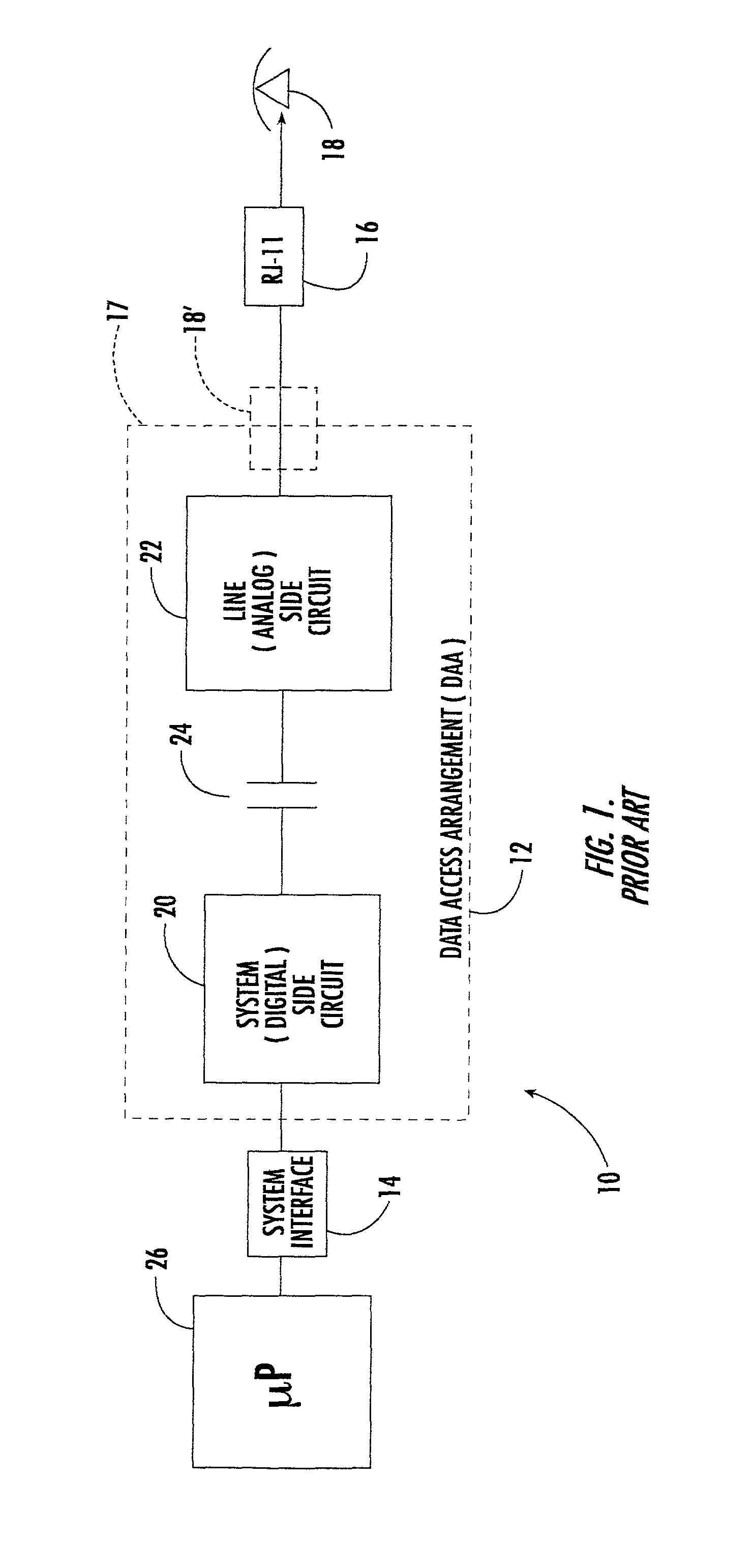
[0019] There shown in FIG. 1 a modem 10 including a data access arrangement (DAA) 12 a system interface 14, and a jack 16. Jack 16 is typically an RJ 11 jack and receives a compatible plug from a typical telephone line 18. The RJ 11 or similar jack may be on the end of a cable remote from DAA 12 as shown or it may be combined with and on the same printed circuit board 17 for example as DAA 12 as shown in phantom at 18. Printed circuit board 17 forms the platform for DAA 12 which includes the system side circuit 20, line side circuit 22 and an isolation circuit 24 here indicated as a capacitive coupling. The host may be any desired system typically the computer or microprocessor 26.

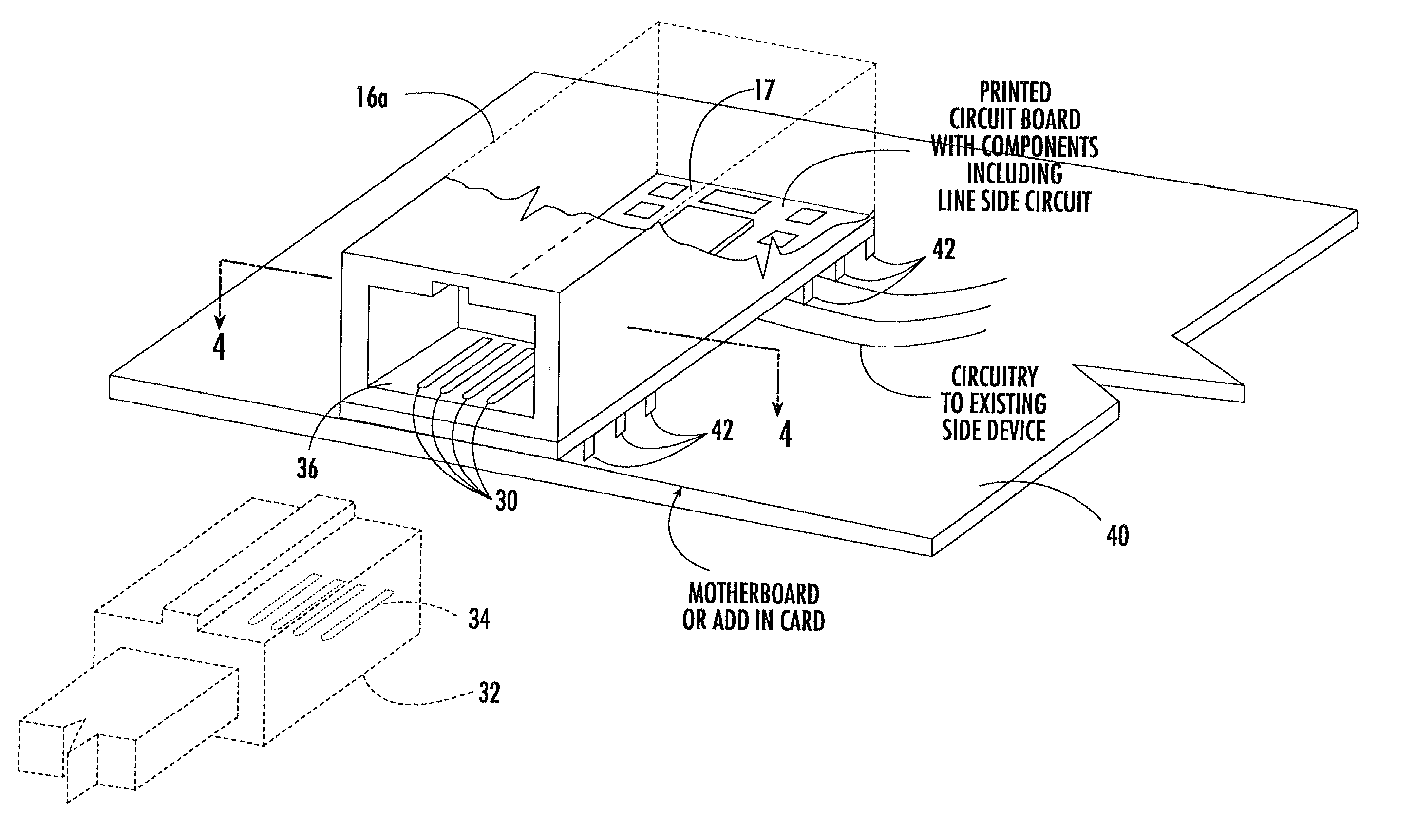
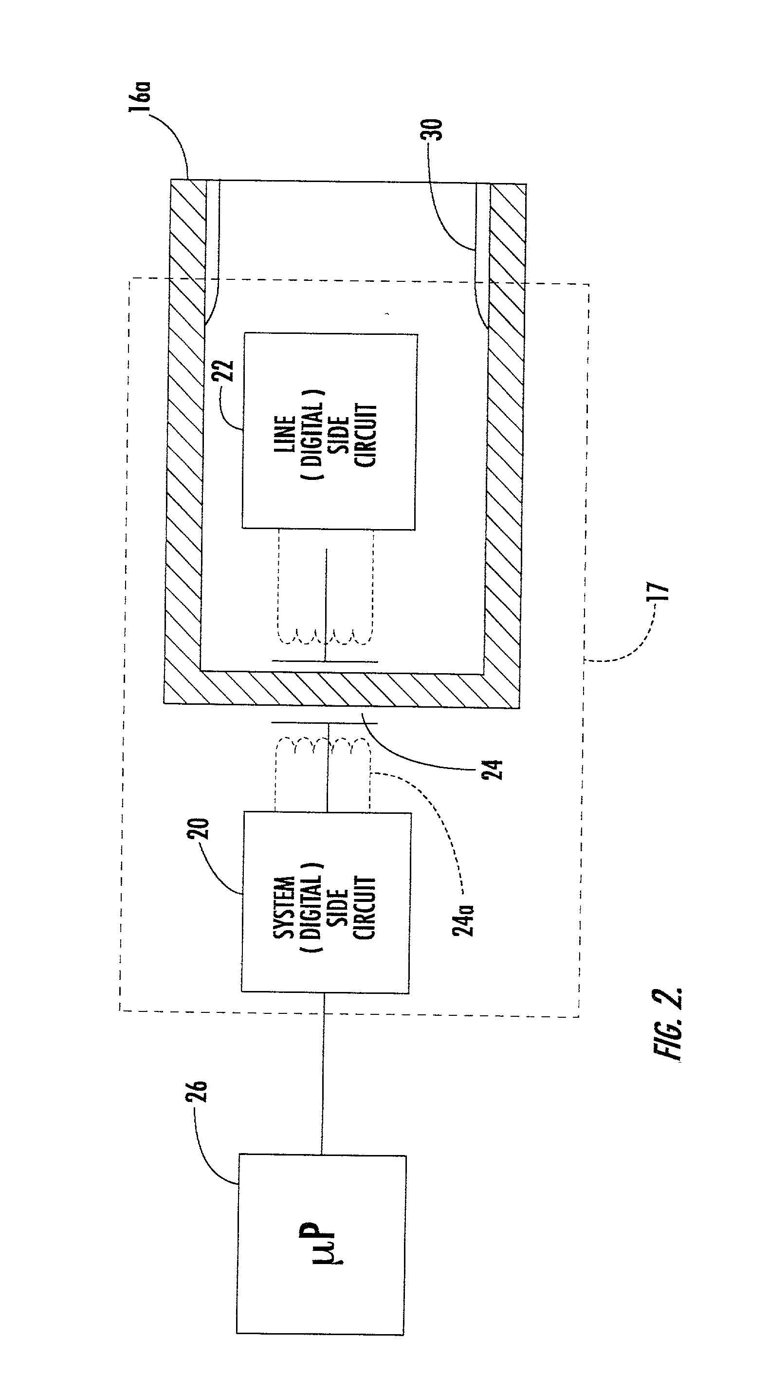
[0020] In accordance with this invention a portion of the data access arrangement is included in jack housing 16a which includes contacts 30, FIG. 2, which engage the mating contacts from a compatible plug such as an RJ 11 or other public service telephone network plug. Line side circuit 22 is included wit...


PUM


Abstract

A jack module with integrated modem interface circuits including a jack housing for receiving a plug; a plurality of contacts in the housing for engaging contacts on a plug; a plurality of terminals on the housing for interconnecting with a mounting member and a line side circuit in the jack housing and interconnecting with the contacts.

Description

[0001] This invention relates to a jack module with integrated modem interface circuits.BACKGROUND OF INVENTION[0002] Historically modems and other devices are connected to telephone networks through an RJ11 plug or similar public service telephone network plug. The modem includes a data access arrangement (DAA) circuit typically supported by a peripheral component interconnect (PCI) card or similar interface. A DAA circuit includes a line side circuit, a system side circuit and an isolation circuit between them. Initially these circuits were implemented with discrete components; more recently these have been constructed with integrated circuits. Mini-PCI's were introduced to reduce the cost, size and power required. With the rapid decrease in cost of computers, PCIs and mini-PCIs were also under downward price pressure and so more and more of the modem including the DAA circuit, system interface and software are being integrated into the system. This has contributed to the simplifi...

Claims


Application Information

Patent Timeline
IPC IPC(8): H01R13/66
CPCH01R13/665H01R2201/04H01R24/62
Inventor LOEB, FREDERICK F.BABICZ, DAVID E.
Owner ANALOG DEVICES INC
Why Eureka
Try Eureka