Receiver

a receiver and receiver technology, applied in the field of receivers, can solve the problems of ambiguity in a relative, disadvantage of using pilot assisted channel impulse response alone, etc., and achieve the effect of improving the estimate of synch tim

Active Publication Date: 2003-01-23
SONY UK LTD +1
View PDF4 Cites 97 Cited by
  • Summary
  • Abstract
  • Description
  • Claims
  • Application Information

AI Technical Summary

Benefits of technology

[0012] Co-pending UK patent applications serial numbers 0027423.3 and 0027424.1 (referred to in the following description as [1]) disclose a receiver having a guard adapted filter processor. The guard adapted filter processor generates a synch time estimate by matching the taps of a filter to the signal samples of the guard period. By exciting the filter with the signal samples, an output signal is produced which represents the channel impulse response. A synch time detector determines the synch time estimate with respect to the earliest of the signal paths of the impulse response. However, as will be explained shortly, in order to set the taps of the matched filter to the signal samples of the guard period it is necessary to have a first estimate of the synch time. Errors in this estimate will result in a reduction of the signal to noise ratio of the representation of the channel impulse response produced at the output of the matched filter. Correspondingly, a reduction in the likelihood of estimating the optimum synch time estimate may result. However, using the pilot assisted tracker to determine accurately the time of arrival of the main signal path provides an improved likelihood of identifying the signal samples of the guard period. Correspondingly, the signal to noise ratio of the output signal from the guard adapted matched filter results in an improvement in the estimate of the synch time with respect to the earliest signal path of the received signal samples.

Problems solved by technology

However as will be explained, an ambiguity exists in a relative time of arrival of signal paths of the channel impulse response with respect to the main signal path.
As such, there is a disadvantage in using the pilot assisted channel impulse response alone.

Method used


Image

  • Receiver
  • Receiver
  • Receiver

Examples


Embodiment Construction

[0028] 1. Example Application: OFDM

[0029] An example embodiment of the present invention will now be described with reference to detecting and recovering data from a COFDM symbol produced for example in accordance with the Digital Video Broadcasting (DVB) standard. The DVB standard is disclosed in a publication by the European telecommunications standards institute number EN300744 version 1.1.2 (1997-08) and entitled "Digital Video Broadcasting (DVB); Frame Structure Channel Coding And Modulation For Digital Terrestrial Television".

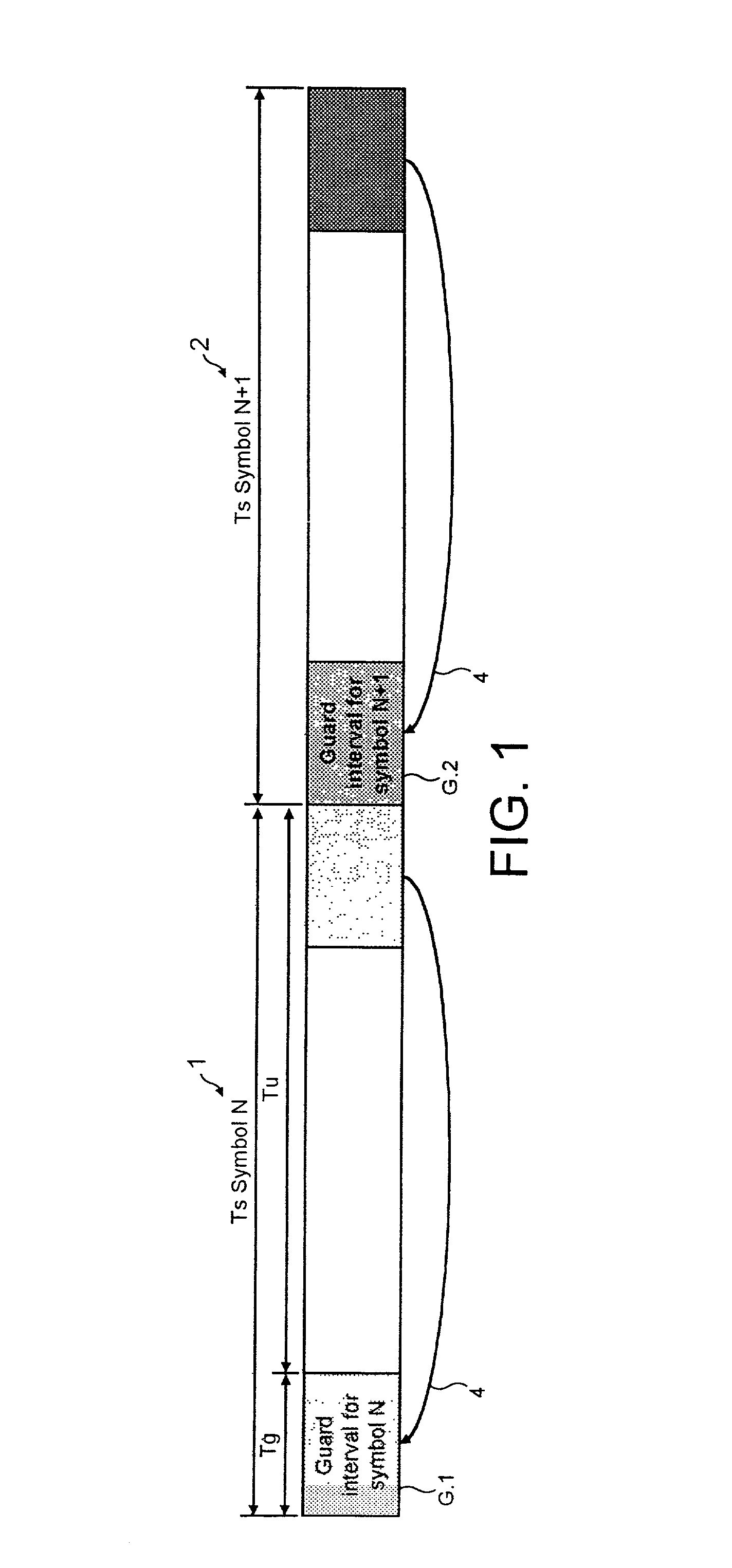
[0030] As already explained, a COFDM symbol which is modulated in accordance with DVB standard is generated by modulating K narrow band carriers in parallel with the data to be communicated. Generally as disclosed in the above referenced ETSI publication, the COFDM symbols are formed in the frequency domain and then converted in the time domain using an Inverse Fourier Transform. A diagram representing the form of the COFDM symbols is shown in FIG. 1. In ...


PUM


Abstract

A receiver determines a symbol synch time for recovering data from a symbol of signal samples generated in accordance with Orthogonal Frequency Division Multiplexing. Each symbol includes a guard period which carries data repeated from a data bearing part of the symbol and pilot signal samples. The receiver comprises a pilot assisted tracker which is operable to determine an adjustment to the symbol synch time from a pilot assisted channel impulse response estimate, a guard adapted filter processor comprising a filter and a filter controller operable to adapt the impulse response of the filter to the signal samples from the guard period. The controller is operable to excite the filter with the symbol signal samples to generate an output signal which provides a further representation of the channel impulse response. A symbol time adjustment estimator is operable to adjust the symbol synch time in accordance with the adjustment provided by at least one of the pilot assisted tracker and the guard adapted filter processor. The receiver provides an improved estimate of the symbol synch time by combining a pilot assisted tracker with a guard adapted filter processor. The pilot assisted tracker estimates the symbol synch time from a channel impulse response estimate generated from pilot signal samples. By combining the synch time adjustment estimated from the pilot assisted channel impulse response, with the adjustment estimated by the guard adapted filter processor, an ambiguity in a relative time of arrival of signal paths of the channel impulse response with respect to the main signal path is obviated.

Description

[0001] The present invention relates to receivers that are operable to detect and recover data from received signal samples. The present invention also relates to methods of detecting and recovering data from received signal samples.BACKGROUND OF INVENTION[0002] Generally data is communicated using radio signals by modulating the data onto the radio signals in some way, and transmitting the radio signals to a receiver. At the receiver, the radio signals are detected and the data recovered from the received radio signals. Typically this is performed digitally, so that at the receiver, the detected radio signals are down converted to a base band representation and converted from analogue form to digital form. In the digital form the base band signals are processed to recover the data. However in order to recover the data, the receiver must be synchronised to the received digital signal samples to the effect that the relative temporal position of the recovered data symbols corresponds ...

Claims


Application Information

Patent Timeline
Patent Type & Authority Applications(United States)
IPC IPC(8): H04L27/26
CPCH04L27/2662H04L27/2695
Inventor ATUNGSIRI, SAMUEL ASANGBENGWILSON, JOHN NICHOLAS
Owner SONY UK LTD
Why Eureka
Try Eureka