Radiometry calibration system and method for electro-optical sensors

a technology of electro-optical sensors and calibration systems, applied in the field of optical systems, can solve problems such as difficult to implement a uniform calibration source for most sensors, complicated system requirements, and high cos

Inactive Publication Date: 2003-02-06
RAYTHEON CO
View PDF3 Cites 15 Cited by
  • Summary
  • Abstract
  • Description
  • Claims
  • Application Information

AI Technical Summary

Problems solved by technology

Focal plane arrays suffer from non-uniformities due to the variations in sensitivity among the detector elements.
Unfortunately, the required system is complicated, bulky, and expensive.
It would be very difficult to implement a uniform calibration source for most sensors--particularly for space applications--due to the package and cost restraints.
Additionally, the uniformity of the source is almost impossible to maintain over a long period of time as a resu

Method used


Image

  • Radiometry calibration system and method for electro-optical sensors
  • Radiometry calibration system and method for electro-optical sensors
  • Radiometry calibration system and method for electro-optical sensors

Examples


Embodiment Construction

[0018] Illustrative embodiments and exemplary applications will now be described with reference to the accompanying drawings to disclose the advantageous teachings of the present invention.

[0019] While the present invention is described herein with reference to illustrative embodiments for particular applications, it should be understood that the invention is not limited thereto. Those having ordinary skill in the art and access to the teachings provided herein will recognize additional modifications, applications, and embodiments within the scope thereof and additional fields in which the present invention would be of significant utility.

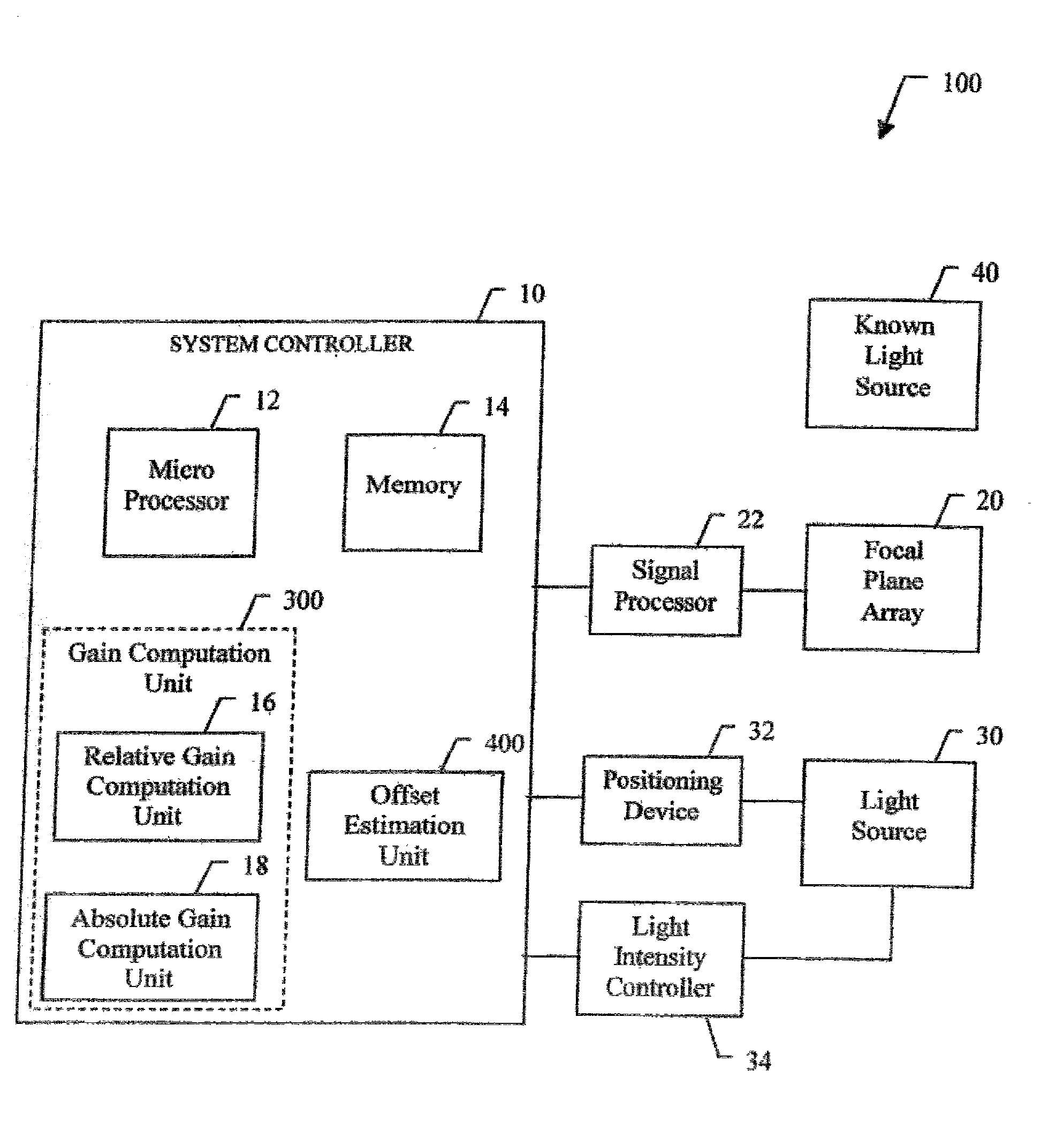
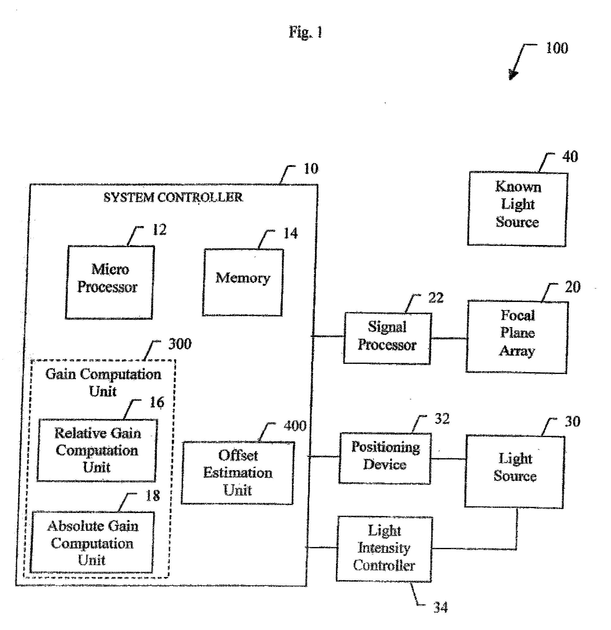
[0020] The present invention provides a system and method for focal plane array (FPA) calibration using an internal non-uniform calibration source. In accordance with the present teachings, a recursive relationship between the relative gain of each detector element (pixel) in the FPA is first calculated using the internal source. Then, the absolute...


PUM


Abstract

A system (100) and method for focal plane array calibration using an internal non-uniform calibration source (30). In the illustrative embodiment, the system (100) includes a first mechanism (16) for calculating a relative gain of each detector element in the focal plane array (20) relative to at least one reference element, a second mechanism (17) for obtaining the absolute gain of the reference element, and a third mechanism (18) for calculating the absolute gains for all other detector elements using the relative gains in conjunction with the absolute gain of the reference element. The relative response of each pixel is calculated from measurements of the response of each pixel using an internal calibration source (30) at two or more different source positions, and two illumination intensities at each position. Measurements using a pair of source positions separated by k pixels establishes the relative response of the ith pixel with respect to the (i+k)th pixel. Through this recursive relationship and other pairs of source position with a different shift vector k, the relative response of every pixel in the FPA can be established. Then, the absolute radiometric calibration of at least one reference pixel is accomplished using a known external source (40), such as a star. The absolute response calibration of each pixel can then be obtained using the recursive relationship in combination with the reference pixels.

Description

[0001] 1. Field of the Invention[0002] The present invention relates to optical systems. More specifically, the present invention relates to systems and methods calibrating focal plane arrays.[0003] 2. Description of the Related Art[0004] A focal plane array (FPA) is an array comprised of several individual detector elements (pixels). Focal plane arrays suffer from non-uniformities due to the variations in sensitivity among the detector elements. These variations must be determined and accounted for in order to achieve proper sensor calibration. Consequently, non-unifrom correction (NUC) measures have been developed for FPA calibration.[0005] Current NUC calibration techniques require a very uniform on-board calibration source to cover the entire focal plane array. With a uniform source, each detector element receives the same source intensity. Variations in the detector outputs are therefore due to variations in detector sensitivity. This information can then be used to calibrate t...

Claims


Application Information

Patent Timeline
IPC IPC(8): G01J1/00G01J1/44G01J1/02G01J5/52G01M11/00H04N5/33H04N5/365H04N5/369
CPCG01J5/52H04N5/33H04N5/3653H04N25/672
Inventor TSAI, CHENG-CHIHCHEN, CHUNGTE W.
Owner RAYTHEON CO
Why Eureka
Try Eureka