
Wheel with rim having seats inclined towards the outside and produced by an extrusion process

a technology of extrusion process and wheel, which is applied in the field of wheels, can solve the problems of increasing the difficulty of mounting and dismounting tires, the risk of unwedging of tire beads, and the difficulty of evacuating

Inactive Publication Date: 2003-02-27
MICHELIN RECH & TECH SA
View PDF2 Cites 2 Cited by
  • Summary
  • Abstract
  • Description
  • Claims
  • Application Information

AI Technical Summary

Benefits of technology

[0013] The wheel according to the invention has numerous advantages. The fact that the rim comprises a plurality of cavities of variable shapes makes it possible to dissociate its radially outer and inner profiles. It is thus possible to associate an inner profile which guarantees no retention of water, ice or various materials with an outer profile having a mounting groove of depth suitable for easy mounting and dismounting of the tire intended to be fitted on the wheel. The cavities permit a substantial reduction in the weight of the rim while retaining an inertia of the axially inner part of the rim which is very satisfactory.
[0016] This manufacturing process has the advantage of being faster than a molding process, and also makes it possible to use materials having mechanical and fatigue properties that are significantly improved compared with the aluminium alloys conventionally used in a molding process.
[0020] According to one advantageous embodiment, the first and second extensions of the rim belong to the axially-outermost cavity of the rim. This embodiment has the advantage of mechanically reinforcing the assembly zone, which also improves its rigidity and facilitates meeting the tolerances of industrial manufacture.

Problems solved by technology

The main difficulties encountered in the case of travelling with a flat tire or at low pressure relate to the risk of unwedging of the beads of the tire and, in particular, the unwedging of the outside bead of the tire mounted on the outside of the vehicle during cornering.
The well-known proposed techniques for avoiding such unwedging, and in particular that consisting of arranging axially to the inside of the outer rim seat a protrusion or hump of low height, do not appear to give complete satisfaction and tend to increase the difficulties of mounting and dismounting the tires.
This wheel, which is optimized in terms of weight, does however have the drawback of, when the outer profile comprises a mounting groove for a tire, permitting the accumulation, beneath the axially outer portion relative to the mounting groove of the inner profile of the rim of the wheel, of all sorts of materials, such as mud mixed to a greater or lesser extent with stones or snow or ice in winter conditions, which are difficult to evacuate.

Method used


Image

  • Wheel with rim having seats inclined towards the outside and produced by an extrusion process
  • Wheel with rim having seats inclined towards the outside and produced by an extrusion process
  • Wheel with rim having seats inclined towards the outside and produced by an extrusion process

Examples


first embodiment

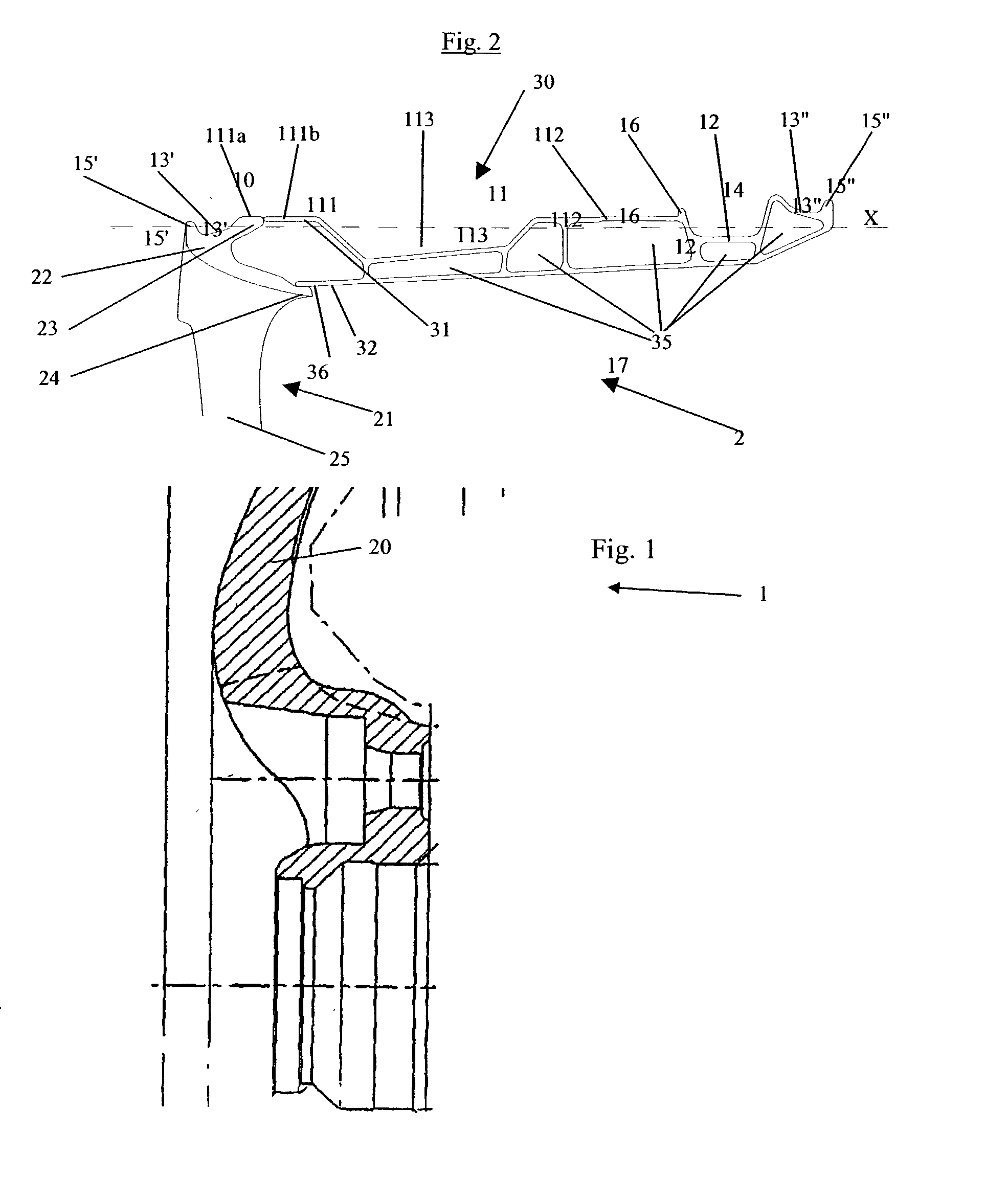
[0031] FIG. 2 shows a wheel according to the invention. In FIG. 2 as in the subsequent figures, like parts are identified by the same reference numbers. The wheel 2, which is an integral wheel, is formed by the assembly of a disc 21 and a rim 30. The radially outer geometry of the wheel 2 is similar to that of the wheel 1 of FIG. 1: there are, in particular, two seats 13' and 13", extended axially externally by two humps 15' and 15", a cylindrical wall comprising two parts 111 and 112 which are separated by a circumferential groove 113, and a mounting groove 12.

[0032] On the other hand, the radially inner profile of the wheel 2 is substantially different from that of FIG. 1, in that the diameter decreases continuously between the inner seat 13" and the convection to the transition zone 25 of the disc 21. As may be seen, this profile does not have any zone favorable to the accumulation of various materials. This result is obtained owing to the presence in the rim of a plurality of ca...

second embodiment

[0043] FIG. 4 shows a wheel according to the invention. The wheel 4 has a radially outer profile adapted to cooperate with a support ring 7 of greatly reduced weight compared with the previous rings. The outer profile of the rim 50 comprises a cylindrical wall or bearing surface 51 directly connecting the part 111a of the outer edge 22 of the disc 21 to the blocking stop 16. The support ring 7 has a reduced width and comprises, in order to remain in place during travel, a circumferential elastic rib 53 intended to fill a suitable circumferential groove 52 formed on the outer profile of the rim 50, when the ring 7 is slipped on to the bearing surface 51.

[0044] FIG. 5 shows a variant of the wheel 4. In this variant 5, the assembly with the disc 21 is ensured, on the side of the rim 60, by two separate cylindrical extensions 65 and 66 as in the case of the wheel 2. To facilitate the slipping of the ring 7 around the cylindrical wall 51, a radially outwardly opening circumferential groo...

third embodiment

[0045] FIG. 6 shows a wheel 6 according to the invention. The wheel 6 is formed by the assembly of a disc 21 and a rim 70. The radially outer profile of the wheel 6 does not comprise a mounting groove. Instead, this profile has at the level of the rim 70 a frustoconical zone 71 arranged between the axially inner seat 13" and the cylindrical bearing surface 51. This frustoconical zone 71 acts as a zone of passage for the second bead of the tire which is intended to come into position on the inner seat 13". This profile permits rapid mounting of the tire and of the support ring 7 on the wheel 6 by slipping the whole around the cylindrical wall 51 axially towards the inside.

[0046] All the examples shown, in non-limitative manner, demonstrate the advantage of the dissociation of the inner and outer profiles of the wheel linked to the process selected for producing the rims. All together, they also demonstrate the flexibility which the designer of the wheel has to meet his needs.


PUM


Abstract

A wheel, having first and second bead seats which are inclined towards the outside and a cylindrical wall intended for supporting a support ring, constituted by the assembly of: a disc comprising a hub bearing surface, a transition zone and a radially outer edge, the geometry of which constitutes the first seat and a first part of the cylindrical wall, and a rim comprising a plurality of cavities and being such that its radially outer wall corresponds to the second seat and to the complementary part of the cylindrical wall; the assembly being effected at the end of the rim on the side of the disc at the level of the cylindrical wall, on one hand, and at the level of the end of the radially inner wall of the rim, on the other hand.

Description

[0001] This is a continuation of international application No. PCT / EP 01 / 14624 filed Dec. 12, 2001, published in French as international publication No. WO 02 / 47923 A2 and claiming priority of French application No. 00 / 16811 filed Dec. 13, 2000.[0002] 1. Technical Field of the Invention[0003] The present invention concerns a wheel, composed of a disc and a rim, for a tire, and able to form, with a support ring for the tread of the tire and the tire, a rolling assembly which may be useful in the case of travelling when the inflation pressure drops abnormally relative to the normal pressure of use (referred to as rated service pressure) or even becomes zero.[0004] 2. The Related Art[0005] The main difficulties encountered in the case of travelling with a flat tire or at low pressure relate to the risk of unwedging of the beads of the tire and, in particular, the unwedging of the outside bead of the tire mounted on the outside of the vehicle during cornering. The well-known proposed te...

Claims


Application Information

Patent Timeline
Patent Type & Authority Applications(United States)
IPC IPC(8): B60B21/00B60B3/04B60B21/02B60B21/10B60B21/12B60C15/02
CPCB60B3/02B60B21/00B60B21/023B60B21/025B60B21/026B60B21/102B60B21/104B60B21/12B60C15/0236B60C15/0247
Inventor EMBERGER, THOMASALFF, DENIS
Owner MICHELIN RECH & TECH SA
Learn More