Devices and methods for noise suppression in pumps

a technology of noise suppression and devices, applied in the field of gear pumps, can solve the problems of affecting the noise generation and transmission, and affecting the overall damping of the noise generated and transmitted, so as to reduce the amount of bubbles flowing

Inactive Publication Date: 2003-02-27
MICROPUMP
View PDF0 Cites 3 Cited by
  • Summary
  • Abstract
  • Description
  • Claims
  • Application Information

AI Technical Summary

Benefits of technology

0010] According to a further disclosed embodiment, noise generated in a magnetic gear pump having (i) a first section that includes a gear assembly for conducting a fluid flow, wherein bubbles are formed in the fluid when the fluid flows in the first section, and (ii) a second section that includes a magnet assembly received in a cup cavity, can be suppressed by substantially reducing the number of bubbles flowing from the first section to the second section. One variant of such a noise-suppression method involves providing at least one passage fluidly connecting the first section and the second section, wherein the passage defines a non-linear fluid-flow path.
0011] The devices and methods disclosed herein are also useful for magnetic pumps in general. In particular, there is disclosed a magnetic pump having a first section that includes at least one fluid-input port and at least one fluid-output port for directing a fluid flow such that bubbles are formed in the fluid when the fluid flows through the first section. The pump also includes a second section comprising a magnet assembly received in a cup cavity, a conduit fluidly connecting the first section and the second section, and means for reducing the amount of the bubbles flowing from the first section to the second section.

Problems solved by technology

Bubble implosion within the interior of a magnet cup is especially problematic due to the relatively thin width (e.g., about 0.1 to about 0.7 mm) of the magnet-cup wall.
In addition, these embodiments substantially interfere with the noise-energy conduction path in the fluid medium passing into the drive section of a pump.
Both of these features contribute to an overall dampening of the noise generated and transmitted by a gear pump.

Method used


Image

  • Devices and methods for noise suppression in pumps
  • Devices and methods for noise suppression in pumps
  • Devices and methods for noise suppression in pumps

Examples


Embodiment Construction

[0021] The following definitions are provided for ease of understanding and to guide those of ordinary skill in the art in the practice of the embodiments.

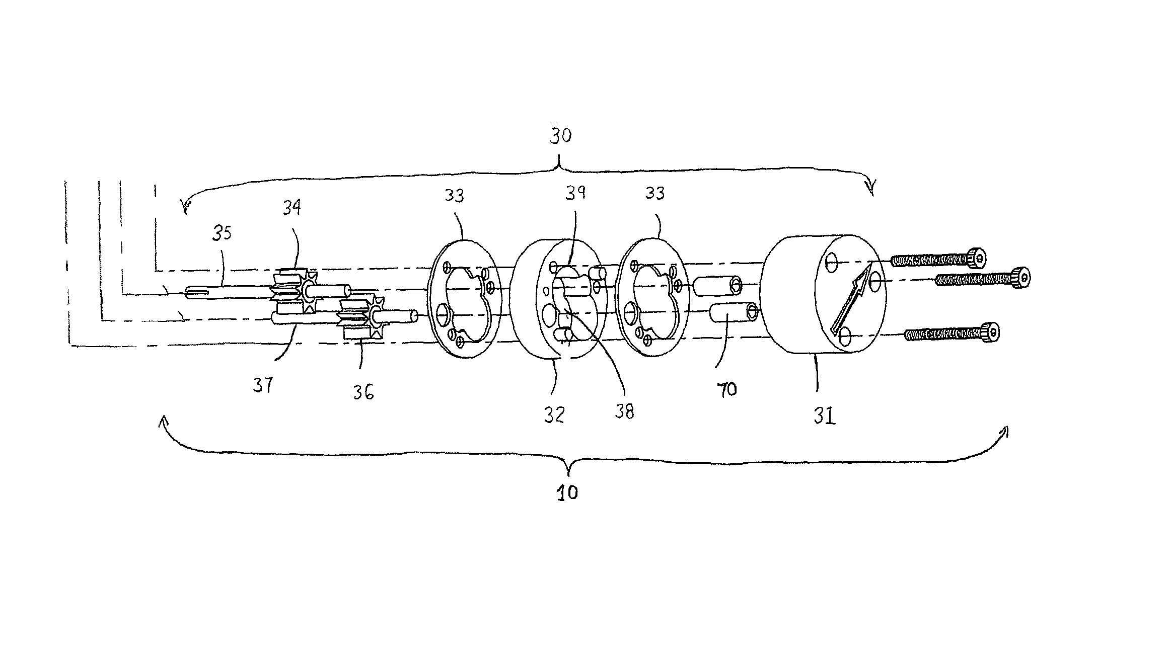
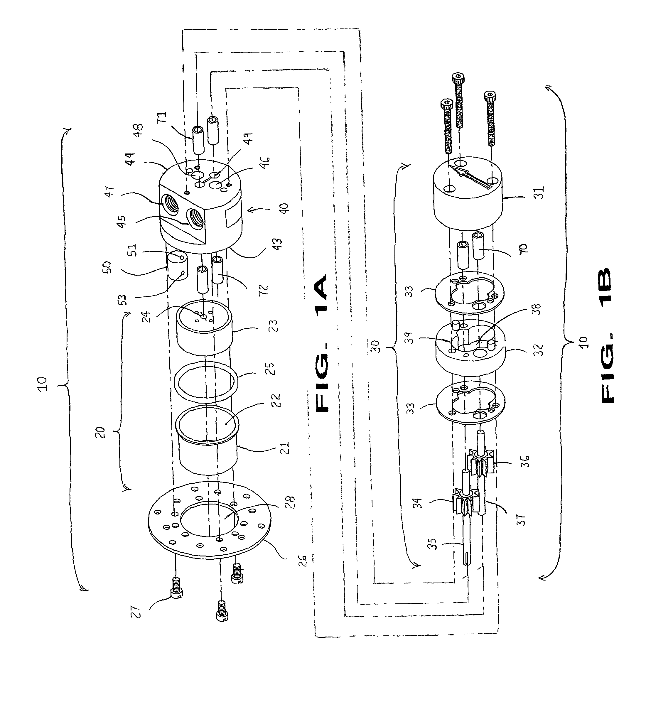
[0022] "Gear pump" encompasses any of various pumps utilizing at least two impellers or rotors (i.e., "gears") that are contrarotated relative to each other in a casing or housing, wherein one of said gears is a "driving" gear and the remaining gear(s) in the pump are "driven" gears. Each gear has multiple teeth or lobes that are oriented radially with respect to the axis of rotation of the gear and that interdigitate (i.e., "mesh") with corresponding teeth or lobes, respectively, in the mating gear. As the gears are contrarotated, fluid enters the spaces between the teeth or lobes of each gear and is transported by the gears to a discharge port. The term "gear pump" also encompasses any of various "internal-gear" pumps as known in the art.

[0023] "Magnetic pump" encompasses magnetically driven and magnetically coupled pumps such a...


PUM


Abstract

Gear pumps are disclosed having a gear-assembly section, a drive-assembly section, and at least one passage fluidly connecting the gear-assembly and drive-assembly sections, wherein the passage includes substantially non-movable walls defining a non-linear fluid-flow path. A particular example is a magnetic gear pump having a gear-assembly section; a section that includes a magnet assembly received in a cup cavity; and a third section located between the gear-assembly and magnet-assembly sections, wherein the third section includes a fluid-input port, a fluid-output port, and at least one conduit for fluidly interconnecting the gear-assembly and magnet-assembly sections; and a member defining at least one non-linear passage in fluid connection with the third section conduit and the cup cavity.

Description

FIELD OF THE DISCLOSURE[0001] The present devices and methods relate to pumps, particularly gear pumps.[0002] Gear pumps as known in the art are particularly advantageous for pumping fluids while keeping the fluids isolated from the external environment. This benefit has been further enhanced by the advent of magnetically coupled drive mechanisms that have eliminated leak-prone hydraulic seals around drive shafts. Gear pumps have been adapted for use in many applications, including applications requiring extremely accurate delivery of a liquid to a point of use. Such applications include, for example, delivery of liquids in medical instrumentation and delivery of liquid ink to continuous ink-jet printer heads.[0003] Gear pumps usually include a gear-assembly section and a drive-assembly section. The fluid flowing through the pump passes through the gear-assembly section. Often there is also a need to provide fluid in the drive-assembly section. For example, the drive assembly may in...

Claims


Application Information

Patent Timeline
Patent Type & Authority Applications(United States)
IPC IPC(8): F04C2/08F04C2/18F04C15/00
CPCF04C2/086F04C2/18F04C15/0069
Inventor BURNS, STEPHEN MICHAELCARR, CHARLES F.
Owner MICROPUMP
Why Eureka
Try Eureka