Device and process for producing metal foam

a technology of metal foam and metal parts, applied in the direction of manufacturing converters, etc., can solve the problems of insufficient adjustment of the pore size or the size distribution of the foam part, the inability to control the size and the size of the foam part to the desired extent, and the inability to reproduce the material behavior in a limited degr

Inactive Publication Date: 2003-03-13
HUTTE KLEIN REICHENBACH
View PDF2 Cites 16 Cited by
  • Summary
  • Abstract
  • Description
  • Claims
  • Application Information

AI Technical Summary

Benefits of technology

[0019] The device can advantageously be designed such that the length by which the outlet opening of the gas feed pipe projects into the melt is at least about 5 times, preferably at least about 10 times, the value of the largest internal dimension of the outlet opening. Particularly effective stable separation criteria of the bubbles in the melt can thereby be achieved.
[0042] With a monomodal size distribution of spatially uniformly distributed pores which is favorable in terms of the isotropy of mechanical properties, a metal foam part according to the invention additionally features an oxide-reinforced pore wall structure, whereby an increased loading capacity in use can be obtained or the service life of components comprising a corresponding metal foam unit can be increased. If the pores of a foam part essentially correspond to individual stabilized bubbles of the corresponding flowable metal foam, the metal foam part according to the invention is suitable for use in components not only in the case of high areal strain but in an excellent manner also in the case of high strain that is applied punctually.

Problems solved by technology

As a result thereof, pores of different diameters are contained in the foam material formed and solidified in this manner, resulting in a scarcely reproducible material behavior.
An adjustment of the pore size or size distribution in the foam part is not thereby possible to a sufficient extent.
All of the known devices for producing metal foam by blowing gas into a melt are disadvantageous in that they have in common that pores or gas bubbles with large differences in dimensions are formed and that their size and size distribution cannot be controlled to the desired extent.
This often results in undesirable relatively high specific gravities and insufficiently reproducible material behavior of the metal foam material.
As mentioned at the outset, attempts have already been made to achieve a defined gas bubble separation from the nozzle or a division of large gas bubbles by a relative motion of the gas feed opening within the metal or by swirling, but this has not produced the desired effect to a sufficient extent.
Although excellent results in individual tests and in short-run production regarding a uniformity of the gas bubble volumes are obtained with a device of the type mentioned above, in tests regarding the feasibility of the provision of metal foam for a large-scale production of components and composite parts for the automotive industry, it has been determined that during a continuous operation the geometry of the device may change as a result of melt corrosion or reaction of the device with the melt.
Thereby stable gas bubble separation criteria in continuous operation may no longer be achievable.
These pores may become the starting points of a material failure during application of mechanical stress, in particular during application of a high punctual pressure.

Method used


Image

  • Device and process for producing metal foam
  • Device and process for producing metal foam
  • Device and process for producing metal foam

Examples


Embodiment Construction

[0051] The particulars shown herein are by way of example and for purposes of illustrative discussion of the embodiments of the present invention only and are presented in the cause of providing what is believed to be the most useful and readily understood description of the principles and conceptual aspects of the present invention. In this regard, no attempt is made to show structural details of the present invention in more detail than is necessary for the fundamental understanding of the present invention, the description taken with the drawings making apparent to those skilled in the art how the several forms of the present invention may be embodied in practice.

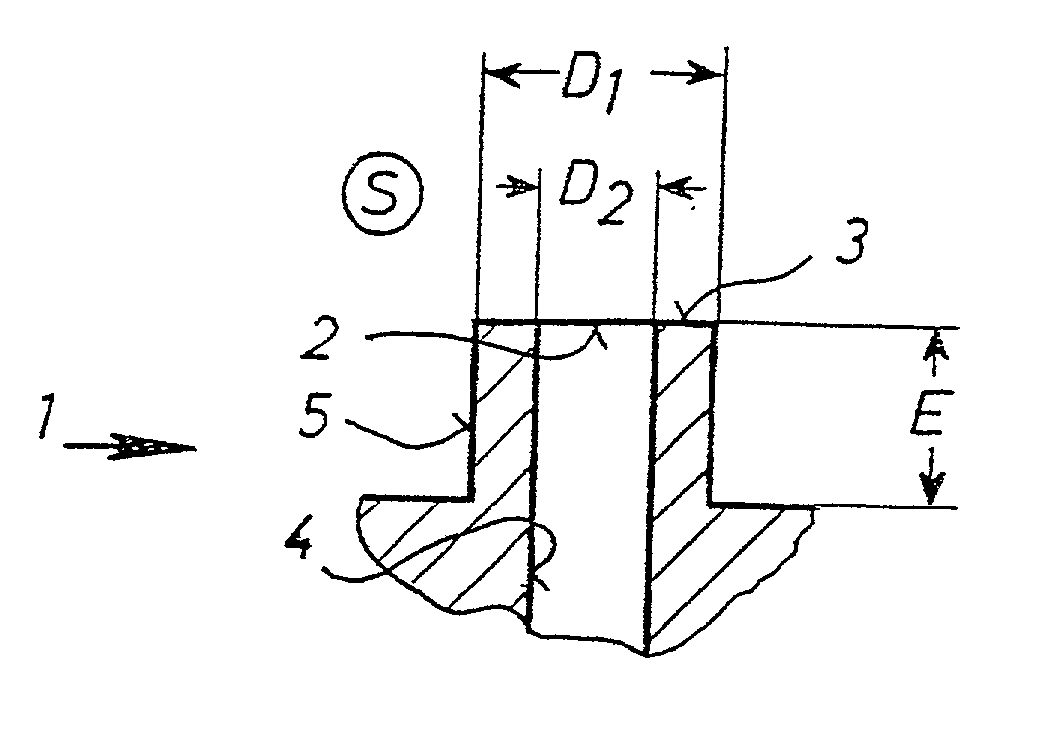
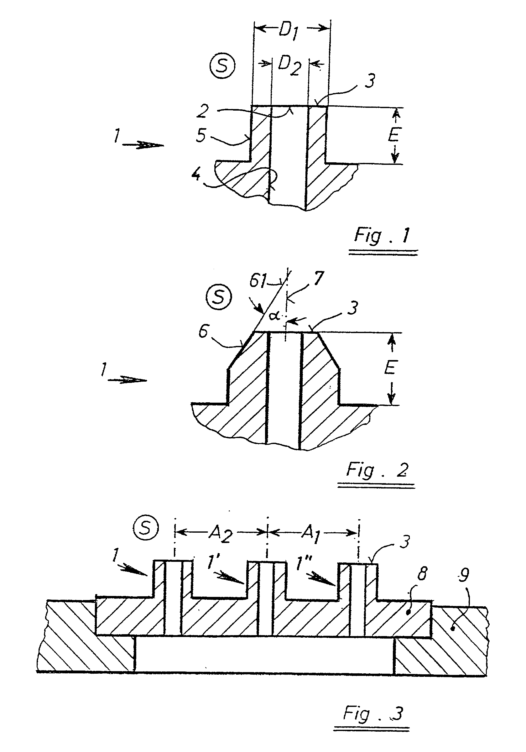
[0052] FIG. 1 shows a gas feed pipe 1 that projects into a melt with a projection length E. Between its inner surface 4 and its outer surface 5 the gas feed pipe 1 shows a constant wall thickness. The pipe face surface 3 projects into the melt S.

[0053] FIG. 2 shows a gas feed pipe 1 with a projection length E into a melt...


PUM

PropertyMeasurementUnit
areaaaaaaaaaaa
areaaaaaaaaaaa
angleaaaaaaaaaa

Abstract

A device for feeding gas in a melt of foamable metal by means of at least one pipe for producing metal foam. The gas insertion pipe projects inwardly into the melt and at the projecting end has a gas outlet having a cross section of 0.006 to 0.2 mm2 and a pipe face area of less than 4.0 mm2. A flowable metal foam has gas bubbles defined by walls of a liquid metal matrix with solid reinforcing particles, and the diameter of the largest gas bubbles divided by that of the smallest gas bubbles is less than 2.5.

Description

[0001] The present application claims priority under 35 U.S.C. .sctn.119 of Austrian Patent Application No. 935 / 2001, filed on Jun. 15, 2001, of Austrian Patent Application No. 936 / 2001, filed on Jun. 15, 2001, and of Austrian Patent Application No. 621 / 2002, filed on Apr. 22, 2002. The entire disclosures of these three applications are expressly incorporated herein by reference.[0002] 1. Field of the Invention[0003] The present invention relates to a device for feeding gas into a melt of foamable metal by means of a pipe to produce metal foam.[0004] The invention further relates to a process for producing metal foam by blowing gas into a foamable metal melt.[0005] 2. Discussion of Background Information[0006] Materials having new property profiles are increasingly required in innovative technology. Metal foam represents such a material. On the one hand, in comparison with a solid material, it has a substantially lower specific gravity, and on the other hand it shows different mecha...

Claims


Application Information

Patent Timeline
Patent Type & Authority Applications(United States)
IPC IPC(8): B22D25/00B22F3/11C22C1/08
CPCB22D25/005B22F3/1103B22F2003/1106B22F2998/00C22C1/08C22C2001/083C22C2001/086C22C32/00C22C1/086C22C1/083
Inventor DOBESBERGER, FRANZFLANKL, HERBERTLEITLMEIER, DIETMARBIRGMANN, ALOIS
Owner HUTTE KLEIN REICHENBACH
Why Eureka
Try Eureka