Plastic vane for a vane-cell vacuum pump

a vane-cell vacuum pump and plastic vane technology, which is applied in the direction of machines/engines, liquid fuel engines, other domestic articles, etc., can solve the problems of individual tolerances of lamination parts, multi-part lamination structure, and harmful effects

Inactive Publication Date: 2003-03-20
ROBERT BOSCH GMBH
View PDF0 Cites 7 Cited by
  • Summary
  • Abstract
  • Description
  • Claims
  • Application Information

AI Technical Summary

Problems solved by technology

A multi-part lamination structure has the disadvantage that the individual tolerances of the lamination parts add up.
This is

Method used


Image

  • Plastic vane for a vane-cell vacuum pump
  • Plastic vane for a vane-cell vacuum pump

Examples


Embodiment Construction

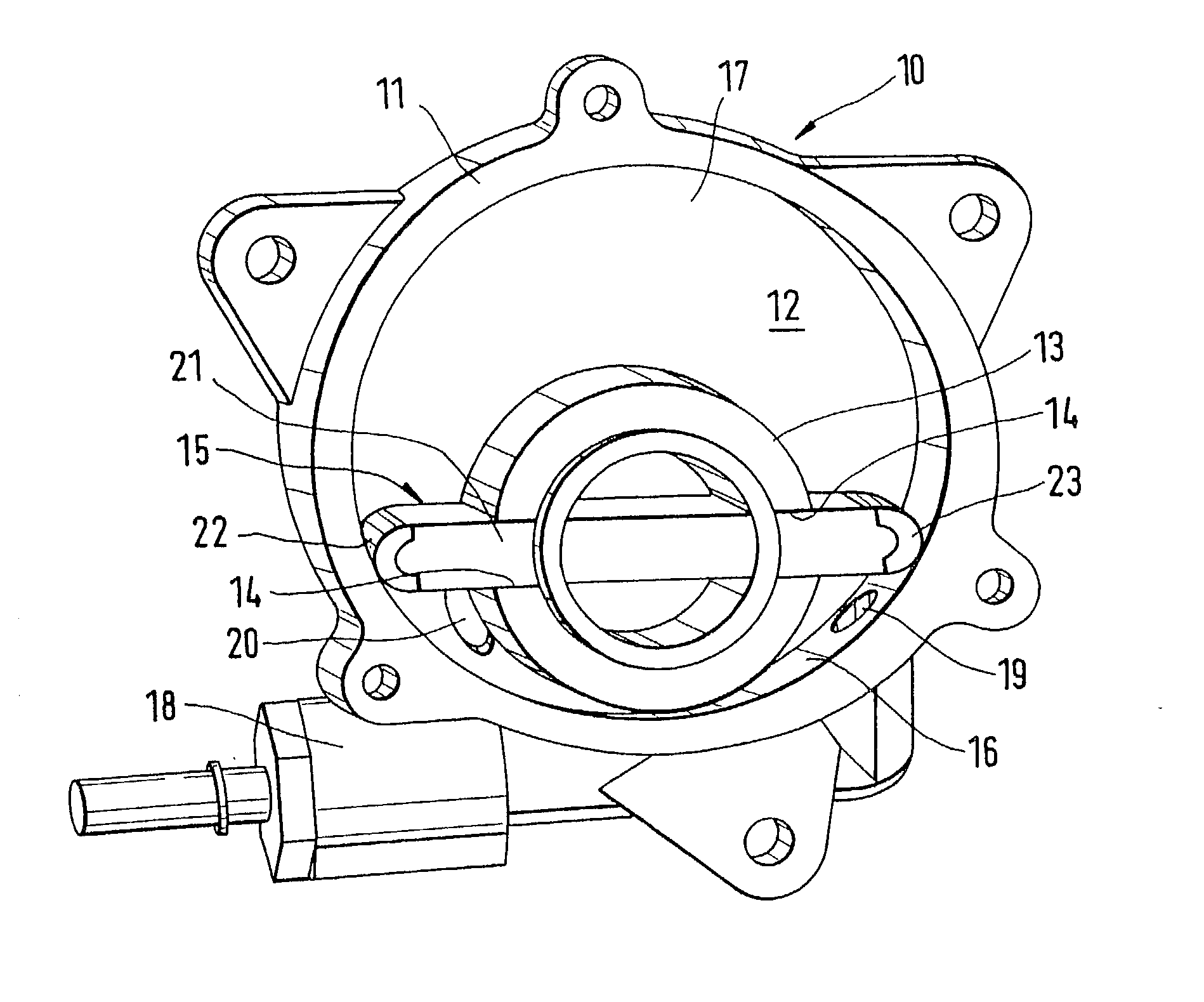
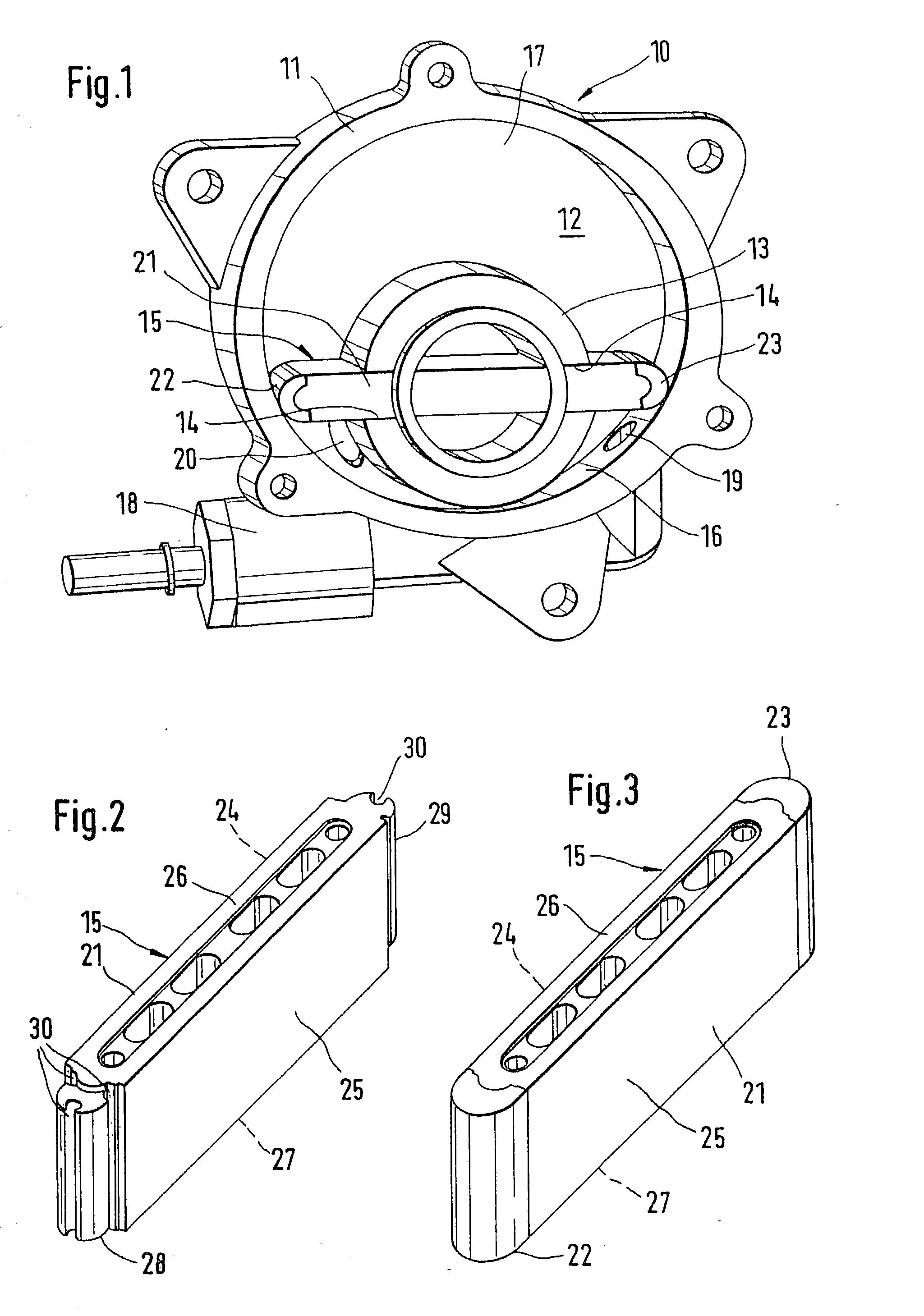
[0013] A vane cell vacuum pump 10 shown in FIG. 1 has a pump housing 11, shown without a cap, with an interior 12 in which a drivable rotor 13 is disposed eccentrically. The rotor 13 is provided with a transversely extending slot 14 for longitudinal guidance of a vane 15 made of plastic. The vane 15 both slidingly and sealingly engages an inner wall 16 on the jacket, an end wall 17, and the cap, not shown, of the pump housing 11. The pump housing 11 also has a suction neck 18 with an inlet opening 19, discharging on the jacket side into the interior 12, and an outlet opening 20 on the face end. The suction neck 18 communicates with a negative-pressure brake booster, not shown, of a vehicle brake system. The function of the vane cell vacuum pump 10 is known and therefore requires no further explanation here.

[0014] The vane 15, embodied in the form of a lamination, is of plastic. Its body 21, shown in FIG. 2 of the drawing, is made from a duroplastic. It is produced by injection moldi...


PUM

PropertyMeasurementUnit
Mechanical strengthaaaaaaaaaa
Thicknessaaaaaaaaaa
Pressureaaaaaaaaaa

Abstract

A vane cell vacuum pump (10) has a rotor (13), in which a plastic vane, which with at least terminal part (22, 23) engages the inner wall (16) of the jacket of a pump housing (11), is guided longitudinally. The body (21) of the vane (15) comprises a duroplastic and is united with the terminal part (22, 23), of thermoplastic, by an injection-molding operation. With the material comprising the body (21), high mechanical strength is attained, while with the material of the terminal part (22, 23), high wear resistance and a low coefficient of friction are attained. The vane cell vacuum pump can be used in a motor vehicle in conjunction with a negative-pressure brake booster.

Description

PRIOR ART[0001] The invention is based on a plastic vane for a vane cell vacuum pump, as generically defined by the preamble to claim 1.[0002] From German Utility Model DE-GM 75 03 397, a cell compressor is known that is equipped with plastic laminations or vanes. While the part of the laminations associated with the rotor of the cell compressor comprises a low-grade material, the terminal part of the laminations, which is associated with a jacket wall of the compressor housing, should conversely comprise a highly wear-resistant material. The parts of the laminations are produced separately from one another and joined together by methods such as adhesive bonding, riveting and welding. The two lamination parts can also be pressed together already during the production process. A multi-part lamination structure has the disadvantage that the individual tolerances of the lamination parts add up. This is especially harmful if laminations with parts of highly wear-resistant material dispo...

Claims


Application Information

Patent Timeline
IPC IPC(8): F04C25/02B29C45/14B29L31/08F01C21/08F04C18/344
CPCF01C21/0881F04C18/3442
Inventor HASERT, WOLFRAMCADEDDU, LEONARDOPILONE, MONICA
Owner ROBERT BOSCH GMBH
Why Eureka
Try Eureka