Hydraulic system

a technology of hydraulic system and hydraulic valve, which is applied in the direction of mechanical equipment, machines/engines, servomotors, etc., can solve the problems of reducing the controllability of the system and delay the response of the hydraulic system

Inactive Publication Date: 2003-03-27
HITACHI LTD
View PDF0 Cites 7 Cited by
  • Summary
  • Abstract
  • Description
  • Claims
  • Application Information

AI Technical Summary

Problems solved by technology

The air in the circuit may delay the response of the hy...

Method used


Image

  • Hydraulic system
  • Hydraulic system
  • Hydraulic system

Examples


Embodiment Construction

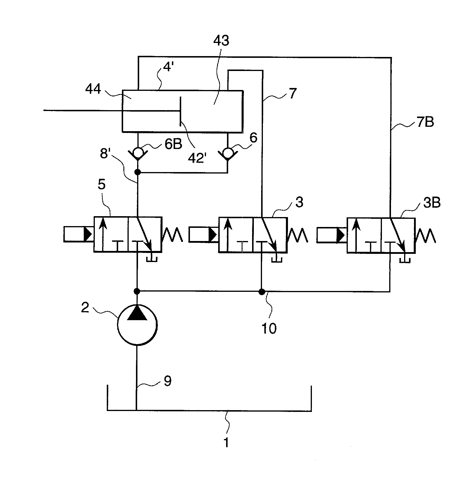
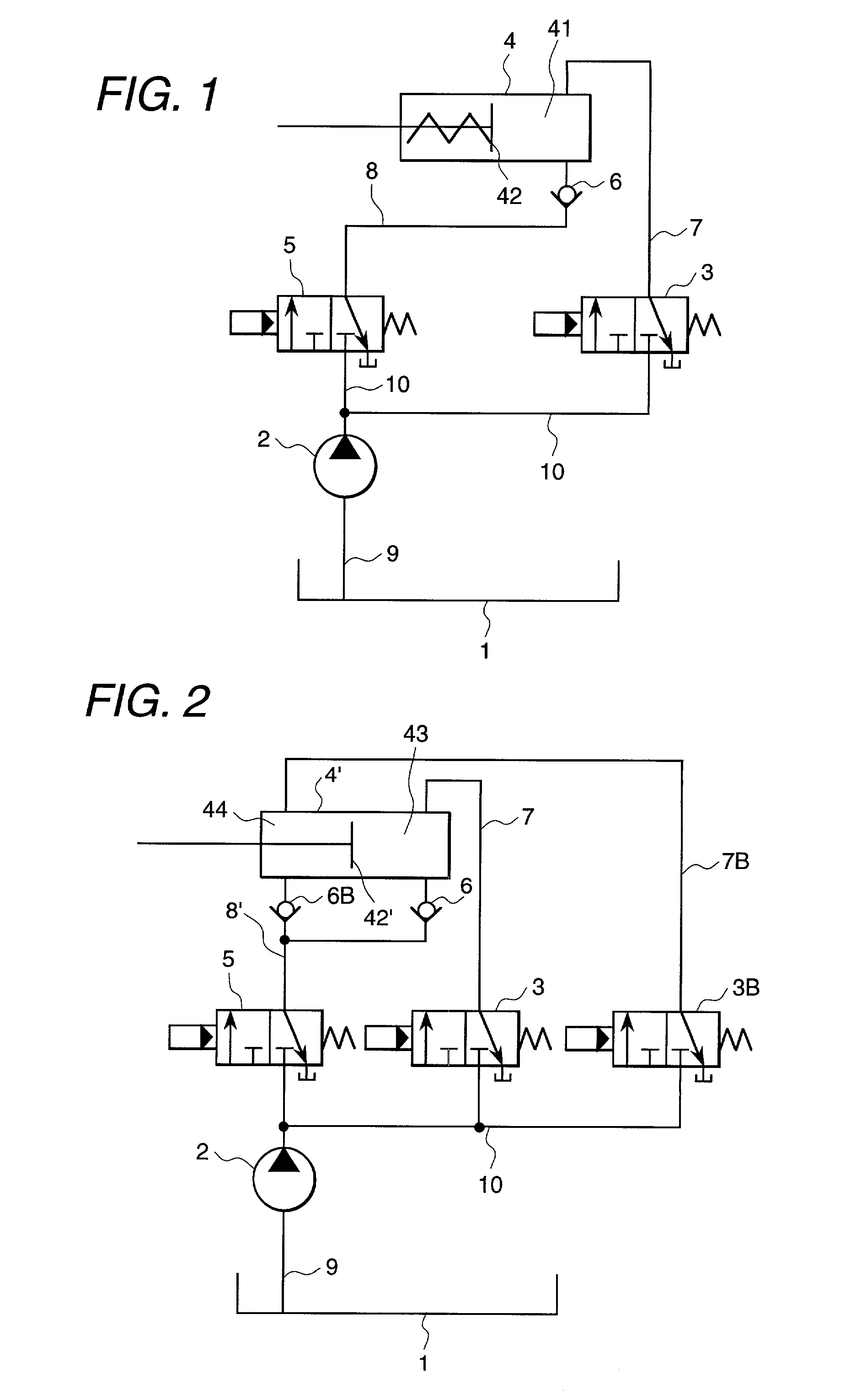
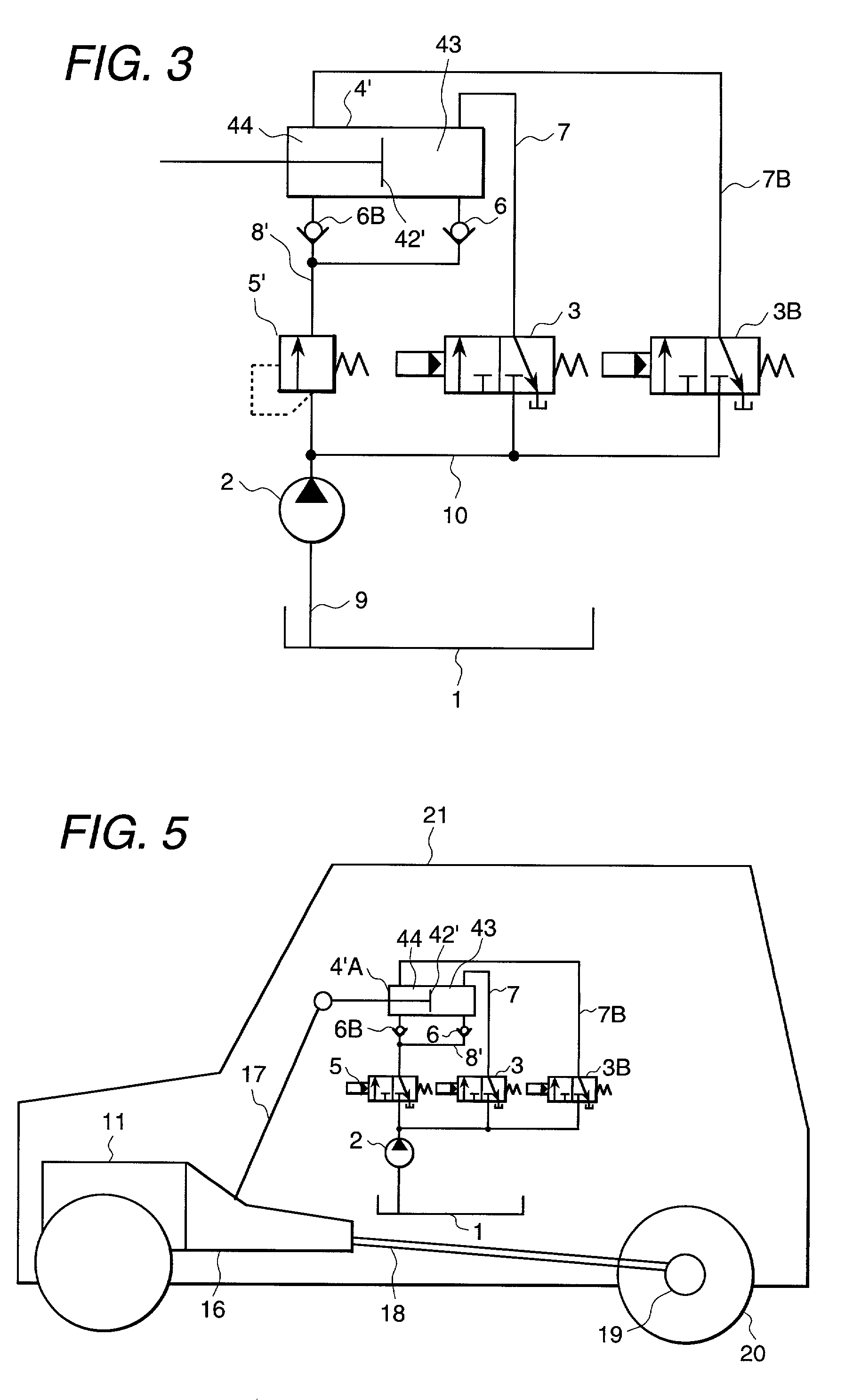
[0014] One embodiment of the present invention will be described below referring to FIG. 1.

[0015] FIG. 1 shows an example of a hydraulic system according to the present invention using hydraulic symbols. A hydraulic tank 1 contains a hydraulic fluid. A hydraulic pump 2, which is driven by a power supply (not shown), can suck the hydraulic fluid from the hydraulic tank 1 via a suction circuit 9 and raise its pressure. The raised high pressure fluid is supplied to a control valve 3 and air sucking control valve 5 through a primary pressure circuit 10.

[0016] The primary pressure circuit 10 is a circuit through which the high pressure hydraulic fluid raised by the hydraulic pump 2 will flow. Thus the primary pressure circuit 10 is also called a high pressure circuit. This primary pressure circuit 10 also includes a circuit which flows a hydraulic fluid having a pressure which is regulated in a pressure valve after being raised in the hydraulic pump 2.

[0017] The (not shown) power supply ...


PUM


Abstract

An hydraulic system comprising an air sucking hydraulic circuit 8, an air sucking control valve 5, and a check valve 6 provided in or before and after the air sucking hydraulic circuit 8, allowing a flow of a hydraulic fluid from the air sucking control valve 5 to the hydraulic actuator 4 and preventing a flow of a hydraulic fluid from the hydraulic actuator 4 to the air sucking control valve 5.

Description

[0001] 1. <Field of the Invention>[0002] The present invention relates to a hydraulic system, more particularly a hydraulic system suited to perform a clutch operation or variable clutch operation of an automobile automatic transmission.[0003] 2. <Prior Art>[0004] A hydraulic system is not hermetically sealed so that an air may enter a hydraulic circuit. In general, the hydraulic circuit is a so-called blind circuit which is closed at a hydraulic side, so that a hydraulic fluid can not circulate in the hydraulic circuit and hydraulic actuator. Thus, the air which enters the hydraulic circuit and hydraulic actuator is unlikely to be exhausted out of the circuit and will remain in them. The air in the circuit may delay the response of the hydraulic system and degrade the controllability of the system. To solve this problem, several ways have been proposed which provide an additional circuit to circulate the hydraulic fluid in the hydraulic circuit to exhaust the air out of...

Claims


Application Information

Patent Timeline
IPC IPC(8): F15B11/00F15B21/04
CPCF15B21/04F16H61/30F16H2061/004
Inventor YAMASAKI, MASARUTOKUO, KENICHIROKUROIWA, HIROSHIOZAKI, NAOYUKI
Owner HITACHI LTD
Why Eureka
Try Eureka