Pop sound reduction circuit and voice output amplification device

a technology of amplification device and output reference potential, which is applied in the direction of electrical transducers, transducer casings/cabinets/supports, gain control, etc., can solve the problems of difficult control of output reference potential, difficult to obtain a transitional operation, and possibility of pop sound

Inactive Publication Date: 2003-03-27
KK TOSHIBA
View PDF0 Cites 27 Cited by
  • Summary
  • Abstract
  • Description
  • Claims
  • Application Information

AI Technical Summary

Problems solved by technology

However, it is actually difficult to obtain a transitional operation in which the output reference potential reaches from the GND potential level to the desired DC potential, by controlling an output switching frequency and a duty ratio.
However, it is difficult to control the output reference potential similarly to the time when the electric power source is turned on, and there is a possibility of occurrence of pop sound due to transitional variations of the switching frequency in the vicinity of the lowest operation voltage of the circuit itself.
However, when the BTL structure is adopted, the number of amplifiers per one channel is doubled, and when the voice output amplification device is powered from two electric power sources, the structure of the power sources become complex.
Therefore, the voice output amplification device encounters a problem of high cost.

Method used


Image

  • Pop sound reduction circuit and voice output amplification device
  • Pop sound reduction circuit and voice output amplification device
  • Pop sound reduction circuit and voice output amplification device

Examples


Embodiment Construction

[0015] Various embodiments of the present invention will be described with reference to the accompanying drawings. It is to be noted that the same or similar reference numerals are applied to the same or similar parts and elements throughout the drawings, and the description of the same or similar parts and elements will be omitted or simplified. In the following descriptions, numerous specific details are set forth such as specific signal values, etc. to provide a thorough understanding of the present invention. However, it will be obvious to those skilled in the art that the present invention may be practiced without such specific details. In other instances, well-known circuits have been shown in block diagram form in order not to obscure the present invention in unnecessary detail.

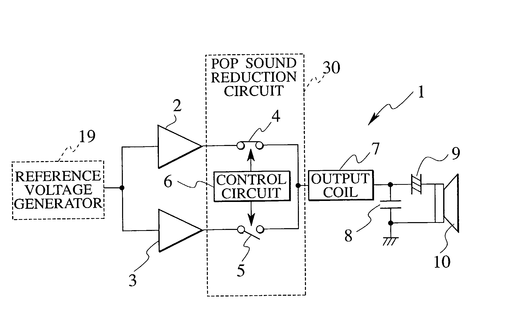
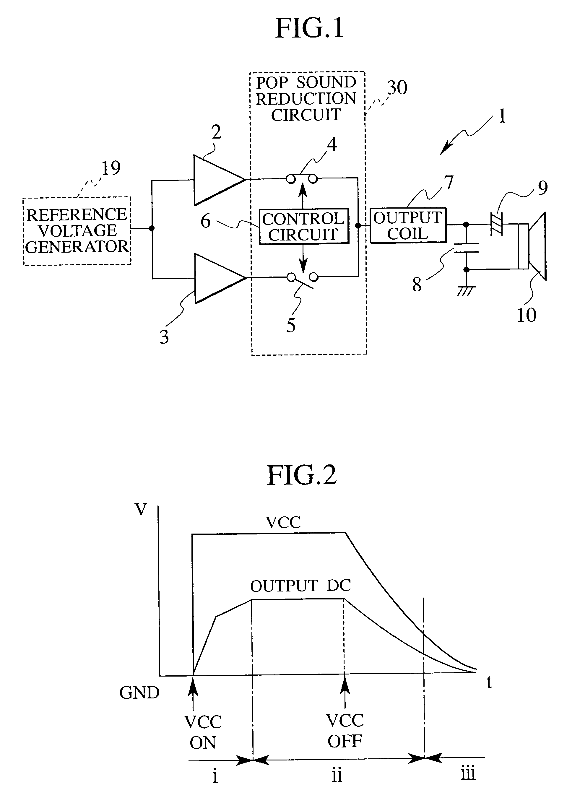
[0016] As shown in FIG. 1, a voice output amplification device 1 comprises a pulse width modulation amplifier (PWM) 2 which sets a reference voltage to an intermediate potential of an amplitude of a pu...


PUM


Abstract

A pop sound reduction circuit comprises a pulse width modulation amplifier configured to amplify a reference voltage to an intermediate amplitude of a pulse width modulated signal, a first switch configured to activate and deactivate the pulse width modulation amplifier, a buffer amplifier configured to generate a DC voltage equal to the reference voltage, a second switch configured to activate and deactivate the buffer amplifier, and a control circuit configured to close and open the first and second switches complementary, depending on a potential in a leading region of the reference voltage which rises from a time of turning-on of a power source as well as a potential in a trailing region of the reference voltage which falls from a time of turning-off of the power source.

Description

[0001] This application is based upon and claims the benefit of priority from the prior Japanese Patent Applications No. P2001-295094, filed on Sep. 26, 2001; the entire contents of which are incorporated herein by reference.[0002] 1. Field of the Invention[0003] The present invention relates to a pop sound reduction circuit which is applied to a voice output device constituted by semiconductor integrated circuits, and more particularly to a pop sound reduction circuit which reduces pop sound generated at the time when power is turned on / off and a voice output amplification device comprising the same.[0004] 2. Description of the Related Art[0005] In terms of a voice output amplification device having a Single Ended Push-Pull (SEPP) circuit structure using a conventional switching system, typified a D-class amplifier, a power supply from one electric power source has been considered to be advantageous from the viewpoint of a circuit scale and cost. In the voice output amplification d...

Claims


Application Information

Patent Timeline
Patent Type & Authority Applications(United States)
IPC IPC(8): H03F1/00H03F1/30H04R3/00H03F3/217H03G3/34H04B1/10
CPCH03F1/305H03F3/217H03G3/348
Inventor MIYAGAKI, KENICHIYAMASHITA, KOUICHI
Owner KK TOSHIBA
Why Eureka
Try Eureka