
Method of producing semi-solid metal slurries

a technology semisolid, which is applied in the direction of metal founding, chemical apparatus and processes, etc., can solve the problems of inability to achieve stable quality of resultant parts, inability to accurately determine the amount of semi-solid metal slurry, and inability to sharply cu

Inactive Publication Date: 2003-04-03
AHRESTY
View PDF3 Cites 14 Cited by
  • Summary
  • Abstract
  • Description
  • Claims
  • Application Information

AI Technical Summary

Benefits of technology

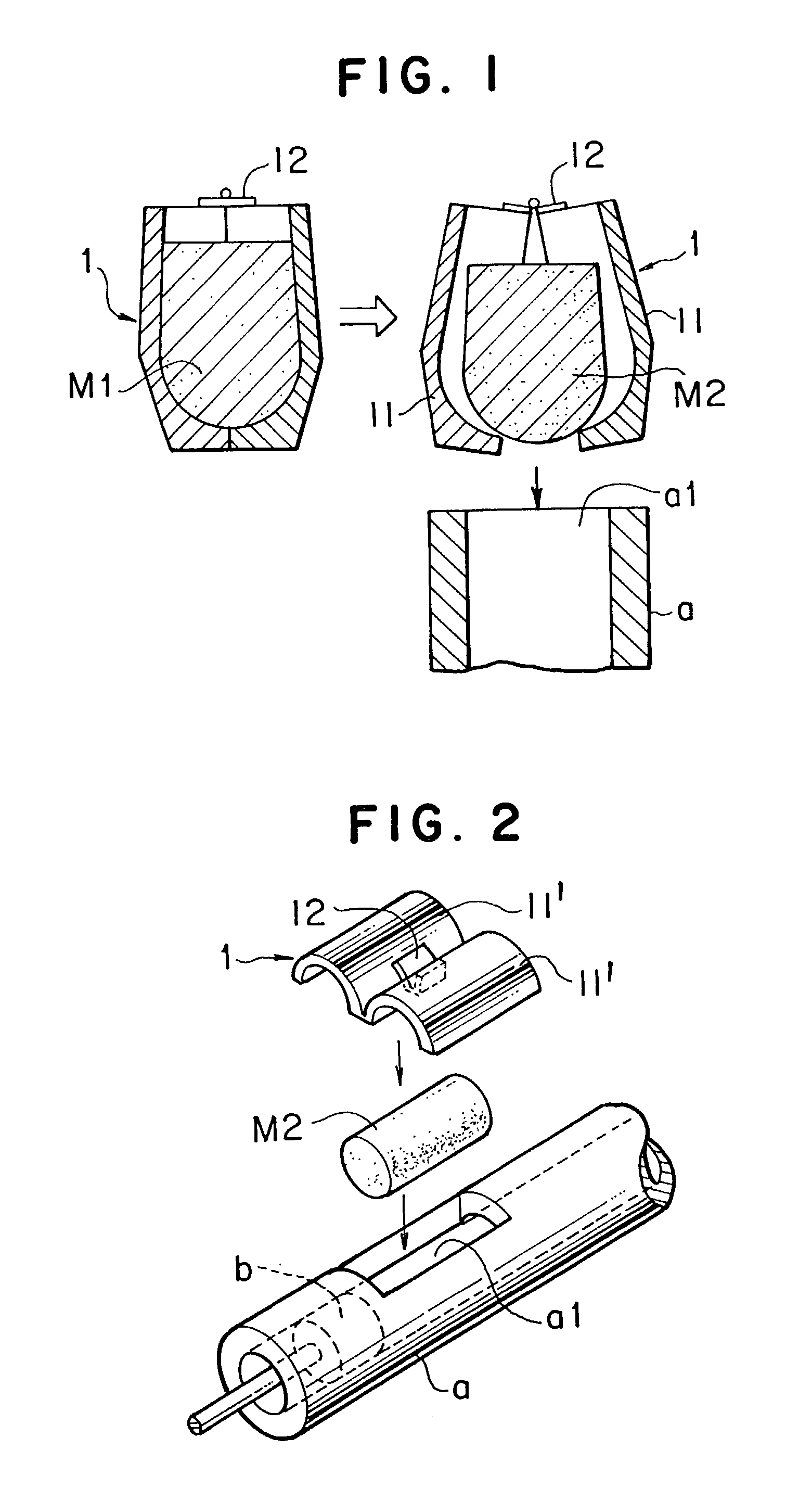
[0006] It is an object of the present invention to provide a semi-solid slurry making method for stably preparing a semi-solid metal slurry with primary crystal particles being fine and almost uniformly non-dendritic (spherical) with a simple system and plain equipment with no particular need of complex procedures and thereafter supplying the slurry stably into a part making machine, the semi-solid slurry making of metals can be easily practiced industrially.

Problems solved by technology

Therefore, it is difficult to sharply cut the semi-solid metal slurry, so that the determination of an amount of the semi-solid metal slurry is inevitably difficult.
For these reasons, the quality of the resultant parts is not stable, disadvantageously.
Furthermore, the semi-solid metal slurry is easily attached and then deposited on a slurry discharge outlet, and therefore, the operation of the opening and closing valve of the slurry discharge outlet immediately fails.
Thus, the stable supply of the semi-solid metal slurry is difficult, and the shape deformation of the resultant semi-solid metal slurry via gravitative attraction is poorer than the deformation of its liquid substance, so that it is difficult to charge the semi-solid metal slurry into the shot sleeve / prechamber of a part making machine.
Additionally, the shape is unstable.
Hence, the charging of the semi-solid metal slurry in its entirety is very difficult, involving difficulty in feeding stably the semi-solid metal slurry into the shot sleeve / prechamber of a part making machine.
Furthermore, the temperature control until the semi-solid metal slurry prepared in a rheomaker is charged into the shot sleeve / prechamber of a part making machine is difficult, disadvantageously.

Method used


Image

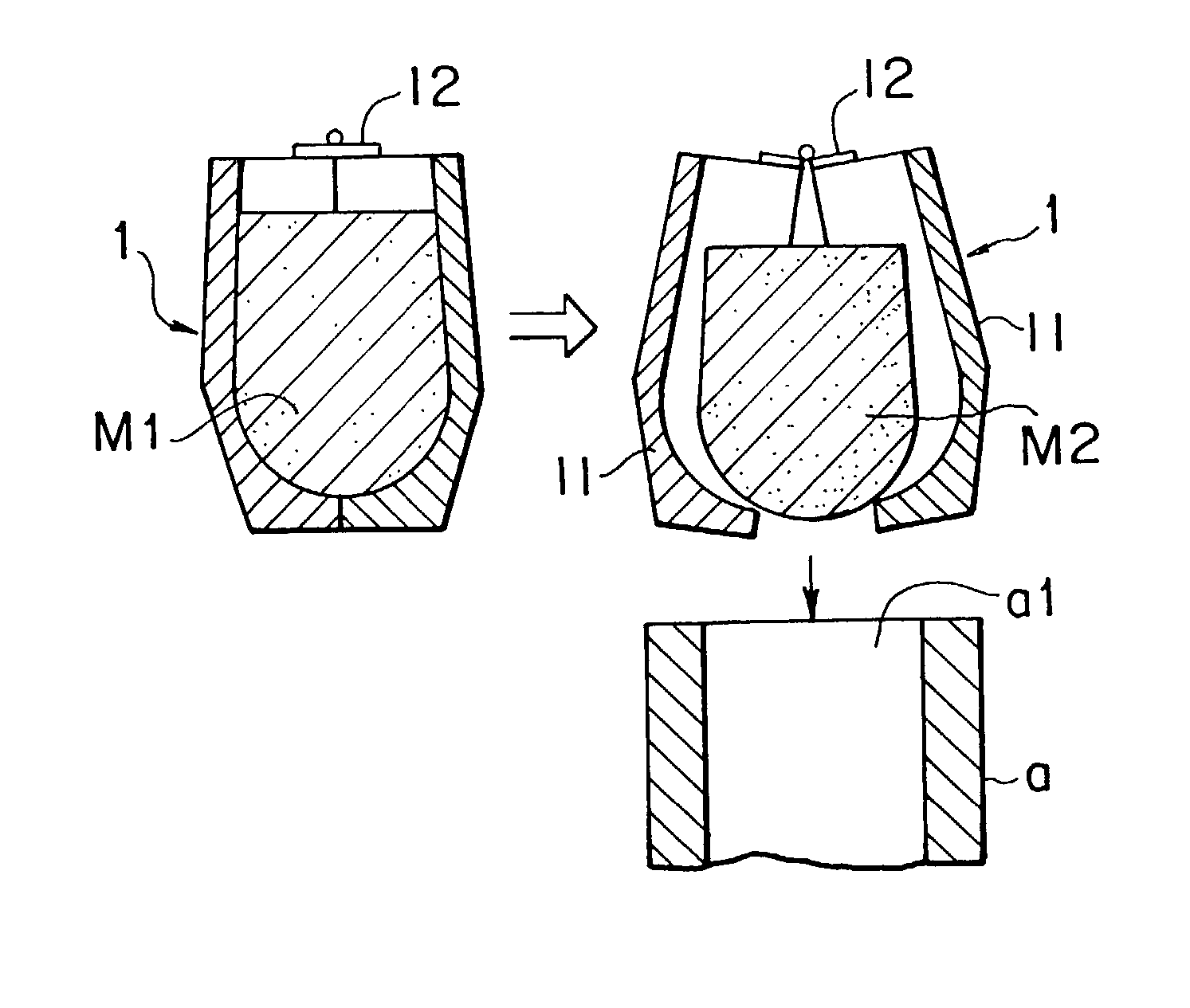
  • Method of producing semi-solid metal slurries
  • Method of producing semi-solid metal slurries
  • Method of producing semi-solid metal slurries

Examples


example 2

[0069] Example wherein a motion is applied on a melted metal placed in a slurry preparing container by mechanically stirring the melted metal;

[0070] At 650.degree. C., the same melted metal (AC4C) as in Example 1 was poured into a thermal insulation container formed in an approximately tubular shape of a diameter of 63 mm and a height of 100 mm, to examine (a) a case wherein the melted metal was mechanically stirred with a ceramics stirring rod by hands when the melted metal was at a temperature between 620.degree. C. to 611.degree. C. (for 39 seconds) and (b) a case wherein the melted metal was similarly stirred when the melted metal reached the liquidus temperature. By spontaneously cooling the melted metals (a) and (b) when the melted metals reached 585.degree. C., the metals were charged into water and were rapidly cooled therein. The metal microstructure was observed. Microscopic photographs of the resultant metal microstructure are shown in FIG. 13.

[0071] Under observation of ...

example 3

[0080] Example wherein a combination of two kinds of motions was applied to the melted metal;

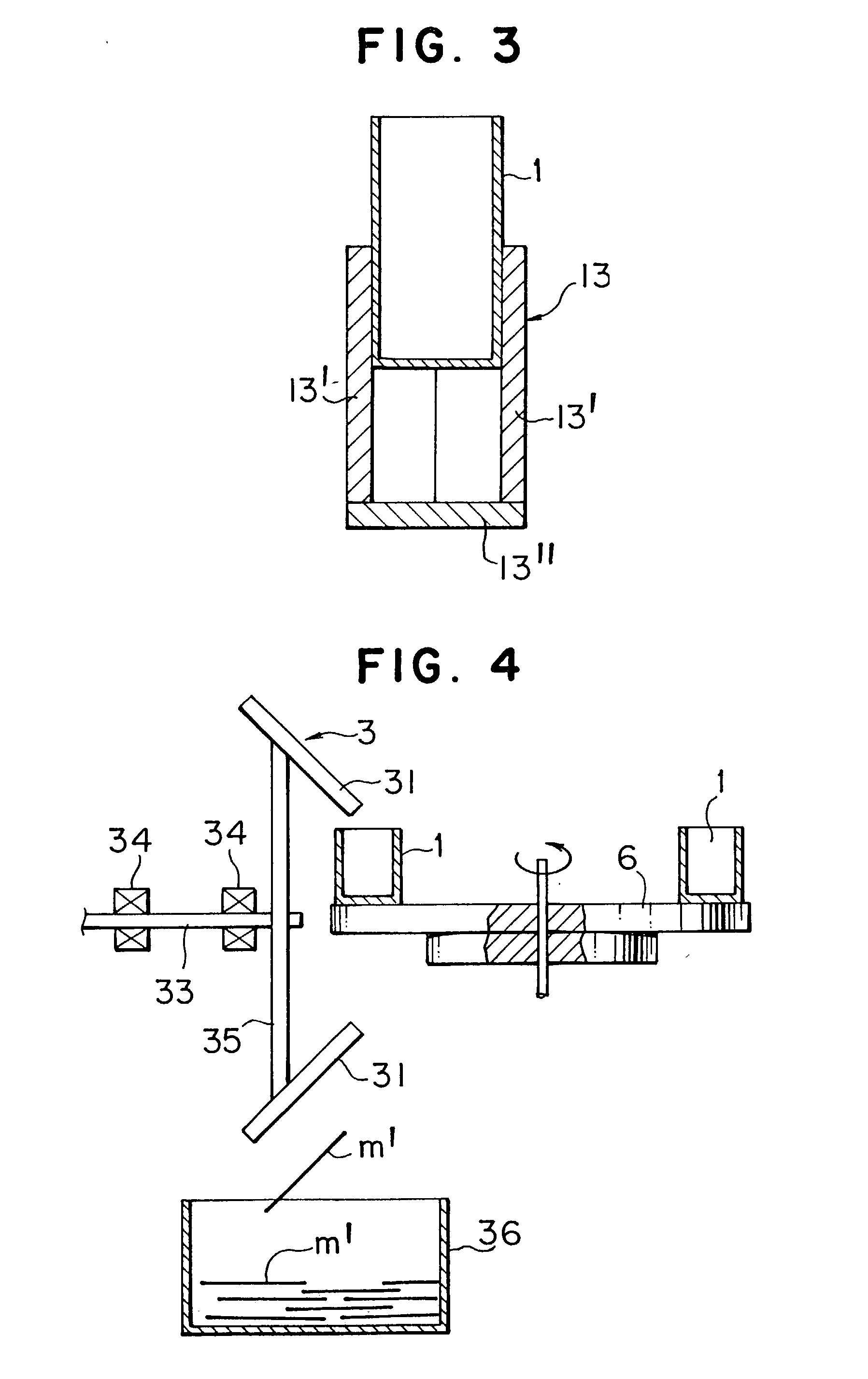
[0081] At 620.degree. C., the same melted metal (AC4C) as in Example 1 was used and (a) poured into a thermal insulation container formed in an approximately tubular shape with a diameter of 63 mm and a height of 100 mm, thereby applying a motion to the melted metal, and (b) by stirring then the melted metal with a high frequency induction stirring system for 10 seconds, a motion was applied to the melted metal. Thereafter, when the melted metal reached 585.degree. C., the melted metal was charged into water for rapid cooling, to observe the metal microstructure in the center and superficial layer region, respectively. The metal microstructure thus obtained is shown in FIG. 18. Under observation of such metal microstructure, the primary crystal was granulated in the metal microstructure at the center, while the metal microstructure in the superficial layer was in a dendritic shape, with no s...


PUM

PropertyMeasurementUnit
Angleaaaaaaaaaa
Temperatureaaaaaaaaaa

Abstract

By determining an amount of a metal to be prepared into a slurry in its liquid state, thereafter applying a motion to the melted metal via a mechanical or physical means when at least a part of the melted metal reaches a temperature below the liquidus temperature and cooling the melted metal in a slurry preparing container to prepare the melted metal into a metal slurry in a semi-solid state, and by concurrently making the semi-solid metal slurry in the slurry preparing container with a shape to be kept almost unchanged, and feeding the semi-solid metal slurry in a state wherein the shape is nearly kept as it is into the shot sleeve / prechamber of the part making machine, a semi-solid metal slurry with the non-dendritic (spherical) primary crystal particles being fine and almost uniform can be fed into the part making machine, with no need of any specifically complex process but with a simple system and plain equipment. Thus, a shaped part with high quality can be produced.

Description

FIELD OF THE INVENTION AND RELATED ART STATEMENT[0001] The present invention relates to rheocasting and thixocasting in mushy / semi-solid state of metals using high pressure part making machines. (Herein, "high pressure part making machine" is simply referred to as "part making machine".)[0002] More specifically, rheocasting is a process of producing a shaped part, comprising cooling a melted metal to a temperature range in which solids and liquids can be present concurrently, and charging the resultant metal slurry into the shot sleeve / prechamber of a part making machine. Thixocasting is a process of producing a shaped part, comprising reheating a solid metal slug to a temperature range in which solids and liquids are concurrently present, and charging the resultant metal slurry into the shot sleeve / prechamber of a part making machine.[0003] Preferably, the metal slurry to be used in the semi-solid process is in a state that the primary crystals are separately distributed throughout...

Claims


Application Information

Patent Timeline
IPC IPC(8): B22D17/30C22C1/00B22D17/00C22C1/02
CPCB22D17/007Y10S164/90C22C1/005C22C1/12B22D17/30
Inventor AOYAMA, SHUNZOLIU, CHISAKAZAWA, TOSHIYUKIPAN, YE
Owner AHRESTY
Learn More