Attaching structure of a brake fluid pressure generator

Inactive Publication Date: 2003-04-10
HONDA MOTOR CO LTD
View PDF5 Cites 5 Cited by
  • Summary
  • Abstract
  • Description
  • Claims
  • Application Information

AI Technical Summary

Problems solved by technology

When this technique is going to be adopted for the vehicle having above described vehicle body construction, since the space for allowing the backward shifting of the engine is required in the engine room, it was unfavorable that parts of large size are arranged in the engine room.
In other words, it is unfavorable that parts of large size are arranged in the engine room, especially between the dash panel and the engine, because the backward shifting of the engine at the time of head-on collision etc is aborted.

Method used


Image

  • Attaching structure of a brake fluid pressure generator
  • Attaching structure of a brake fluid pressure generator
  • Attaching structure of a brake fluid pressure generator

Examples


Embodiment Construction

[0016] The preferred embodiment of attaching structure of the brake fluid pressure generator according to the present invention will now be described by referring to the attached drawings.

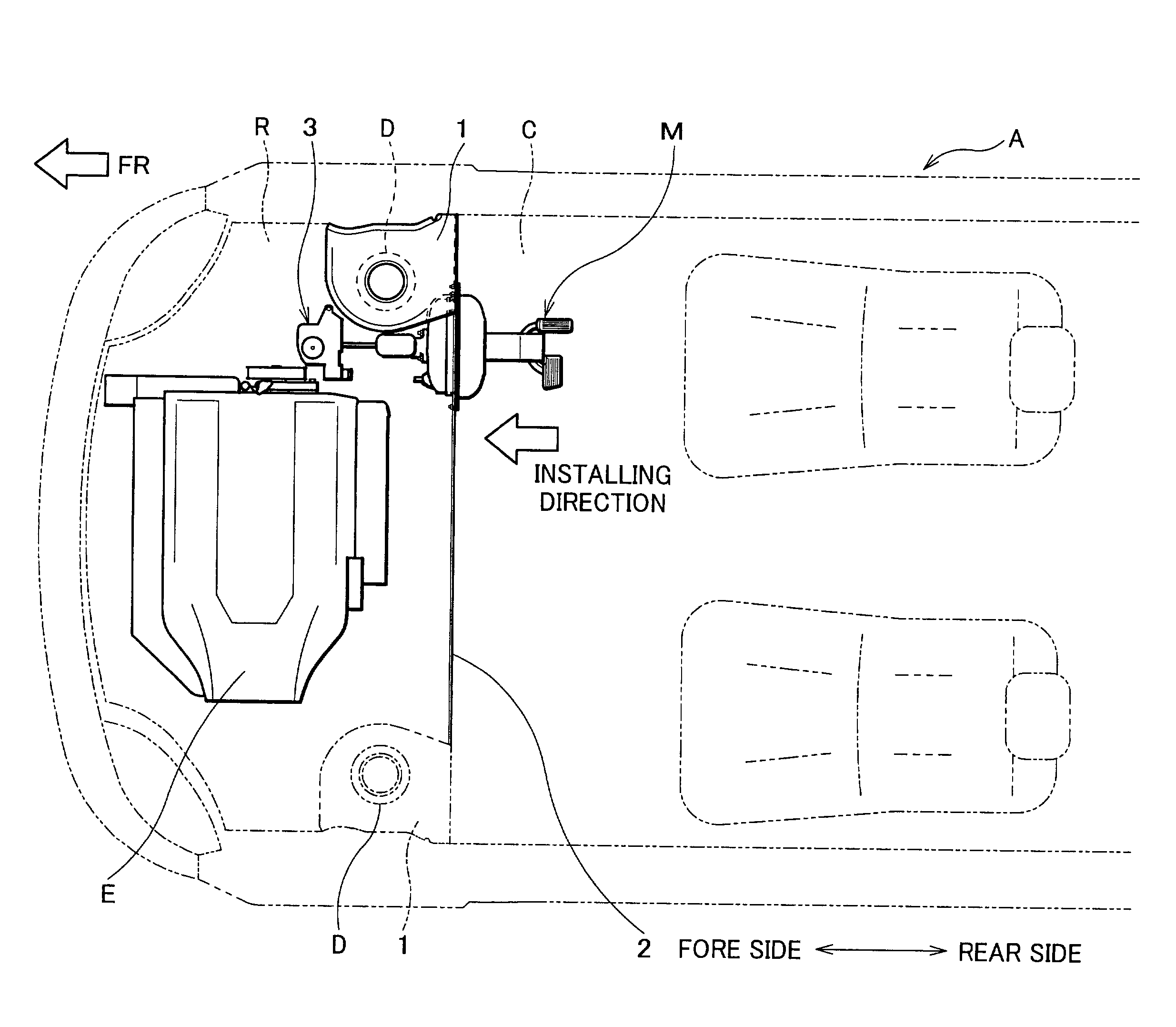
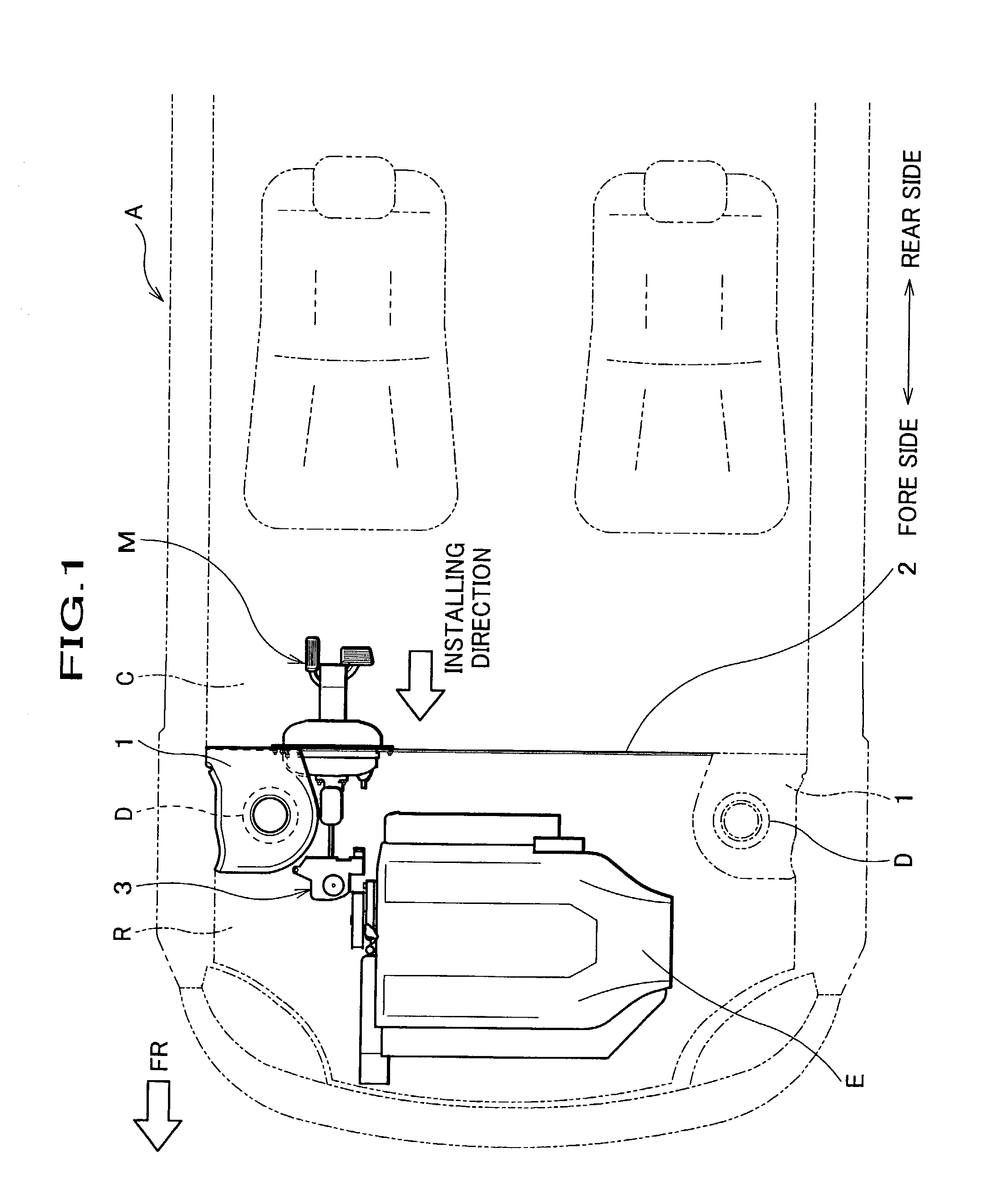
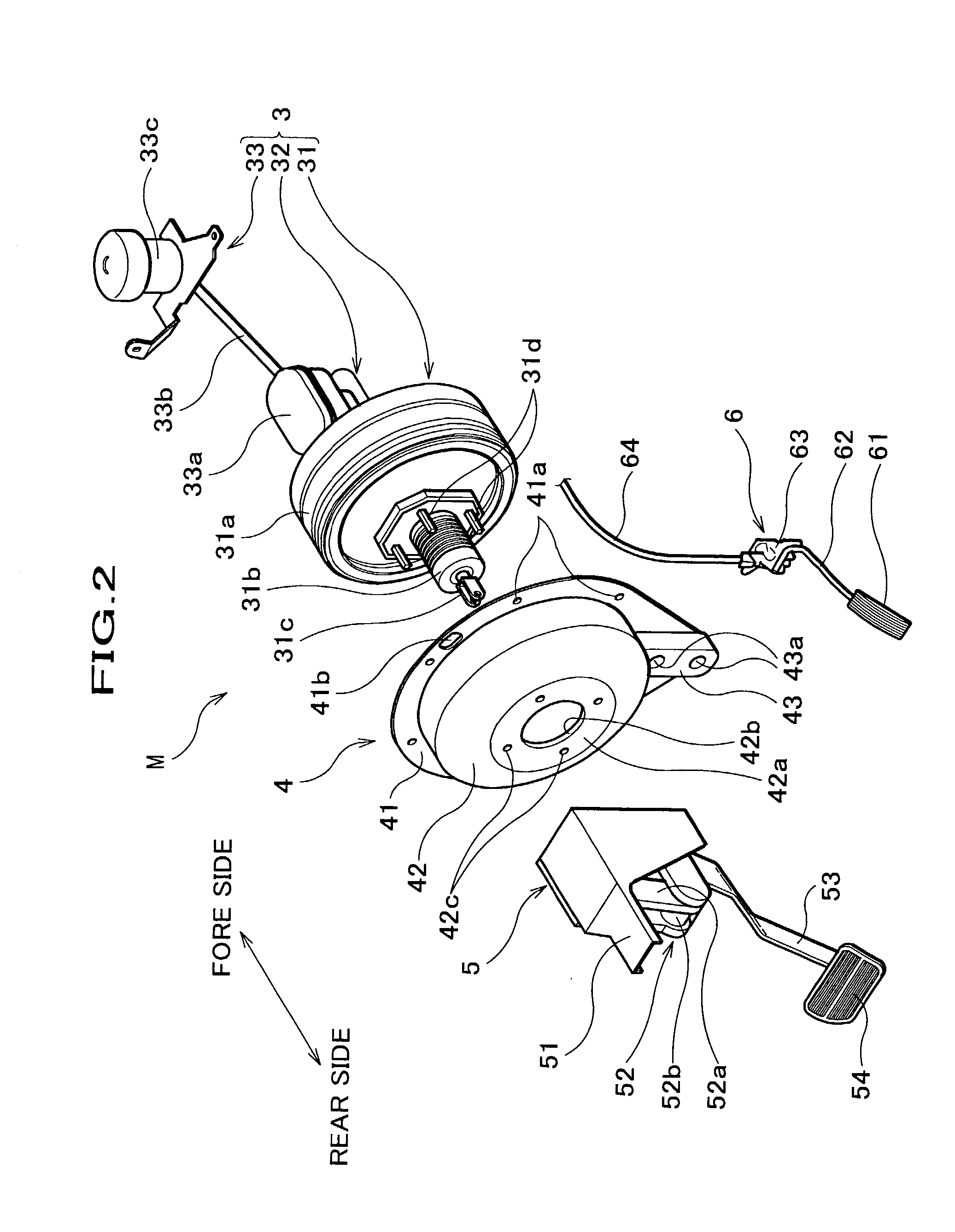
[0017] FIG. 1 is a schematic plan view of a vehicle adopting the attaching structure of the brake fluid pressure generator according to the present invention. FIG. 2 is a perspective view showing the whole pedal module according to the present embodiment. FIG. 3 is a front side view of the brake fluid pressure generator viewing form the fore direction with respect to the vehicle. FIG. 4 is an enlarged plan view showing the principal part of the attaching structure of the brake fluid pressure generator shown in FIG. 1.

[0018] As shown in FIG. 1, a vehicle A has a cabin C, an engine room R and an engine E. The cabin C is a room for passengers and a driver of a vehicle. The engine room R is disposed in front of the cabin C and accommodates the engine E at the center thereof.

[0019] In this vehicle A, a ...


PUM


Abstract

The present invention relates to an attaching structure of a brake fluid pressure generator on the vehicle. This brake fluid pressure generator is attached to a dash panel provided at near the rear side of a damper housing, by which a compartment of a vehicle is divided into a cabin and an engine room. In the present invention, an installation hole, through which the brake fluid pressure generator is inserted, is formed on the dash panel at the outer side in the width directions with respect to the engine. And a mounter, which accommodates part of the brake fluid pressure generator at least, is used for detachably attaching the brake fluid pressure generator to the dash panel from the cabin side. Thereby, part of the brake fluid pressure generator is positioned at the rear side than the dash panel, and the outer diameter figure of the brake fluid pressure generator is positioned so that it might be overlapped with the damper housing when looked from the fore side direction with respect to the vehicle.

Description

[0001] 1. Field of the Invention[0002] The present invention relates to an attaching structure of a brake fluid pressure generator to be attached to the dash panel by which the car body construction is divided into an engine room and a cabin. More specifically, the present invention relates to an attaching structure of a brake fluid pressure generator to be attached to the dash panel locating at the vicinity of the damper housing.[0003] 2. Related Art[0004] As a well-known vehicle body construction for making the cabin space as wide as possible, conventionally, the vehicle body construction, in which a dash panel dividing the inside space of a vehicle into an engine room and a cabin space is positioned as forward as possible, has been known. Especially, most widened cabin space can be obtained in the vehicle body construction, in which the dash panel is located near the damper housing, into which the damper of suspension for left and right wheel is provided.[0005] As one of measures...

Claims


Application Information

Patent Timeline
IPC IPC(8): B60T13/567B62D25/14B60T13/52
CPCB60T13/567Y10T74/20528B62D25/14
Inventor KAWAKAMI, HIROOOTANI, TORUTSUJINO, GOROMIYAHARA, KEISUKEMOMOZU, MASATERU
Owner HONDA MOTOR CO LTD
Why Eureka
Try Eureka