Apparatus for thermosetting thermoplastic tubes

a thermoplastic tube and thermosetting technology, applied in the field of thermosetting thermoplastic tube apparatus, can solve the problems of unsatisfactory use, undesirable environmental impact, and overall operation that is messy, and achieves the effects of reducing thermal deformation of straight sections, reducing heat absorption and heat energy of tubes, and reducing environmental impa

Inactive Publication Date: 2003-04-10
MARTINREA IND INC
View PDF0 Cites 1 Cited by
  • Summary
  • Abstract
  • Description
  • Claims
  • Application Information

AI Technical Summary

Benefits of technology

[0017] In practice, as the formers with their attached thermoplastic tube are conveyed through the oven interior, the absorbent coating on the former locally increases the heat absorption and heat energy of the tube in the area around the bends of the former in an amount sufficient to reset the elastic memory of the tube at the bend location. In doing so, the absorbent coating relatively quickly heats the bent portions of the thermoplastic tube to a point of thermal deformation. Conversely, the straight sections of the former, i.e. the sections where a bend of the thermoplastic tube is undesired, heat less quickly and also remain at a cooler temperature thus minimizing thermal deformation of the straight sections of the thermoplastic tube and likewise minimizing possible collapse of the thermoplastic tube due to thermal deformation.

Problems solved by technology

A primary disadvantage of utilizing a vat of heated liquid is that the overall operation was necessarily messy since liquid from the vat would drip on the workplace around the vat.
A further disadvantage of this previously known method of heating the formers with the thermoplastic tubing is that it is necessary to periodically dispose of the liquid in the vat.
This, in turn, can result in an undesirable environmental impact where materials, such as glycol, are used in the vat.
This previously known apparatus, however, has not proven wholly satisfactory in use.
One disadvantage of this previously known apparatus was that the radiant heaters were arranged in the oven so that the radiant heaters concentrated the heat output from the heaters only at the areas of the former at which a bend was desired.
Furthermore, this previously known device was inappropriate when formers of different shapes were simultaneously conveyed through the oven.
These previously known devices, however, have also not proven wholly satisfactory in use.
A primary disadvantage of these previously known devices is that the entire thermoplastic tube was subject to radiant deformation including not only the bend areas of the former, but also the straight sections of the thermoplastic tube between the bends.
The thermal deformation of the straight sections of the thermoplastic tube, however, may actually result in undesirable collapse of the thermoplastic tube.
While internal inserts into the thermoplastic tube may be utilized to minimize collapse of the thermoplastic tube due to thermal deformation, the use of such inserts are time consuming, labor intensive and therefore undesirably expensive.

Method used


Image

  • Apparatus for thermosetting thermoplastic tubes
  • Apparatus for thermosetting thermoplastic tubes

Examples


Embodiment Construction

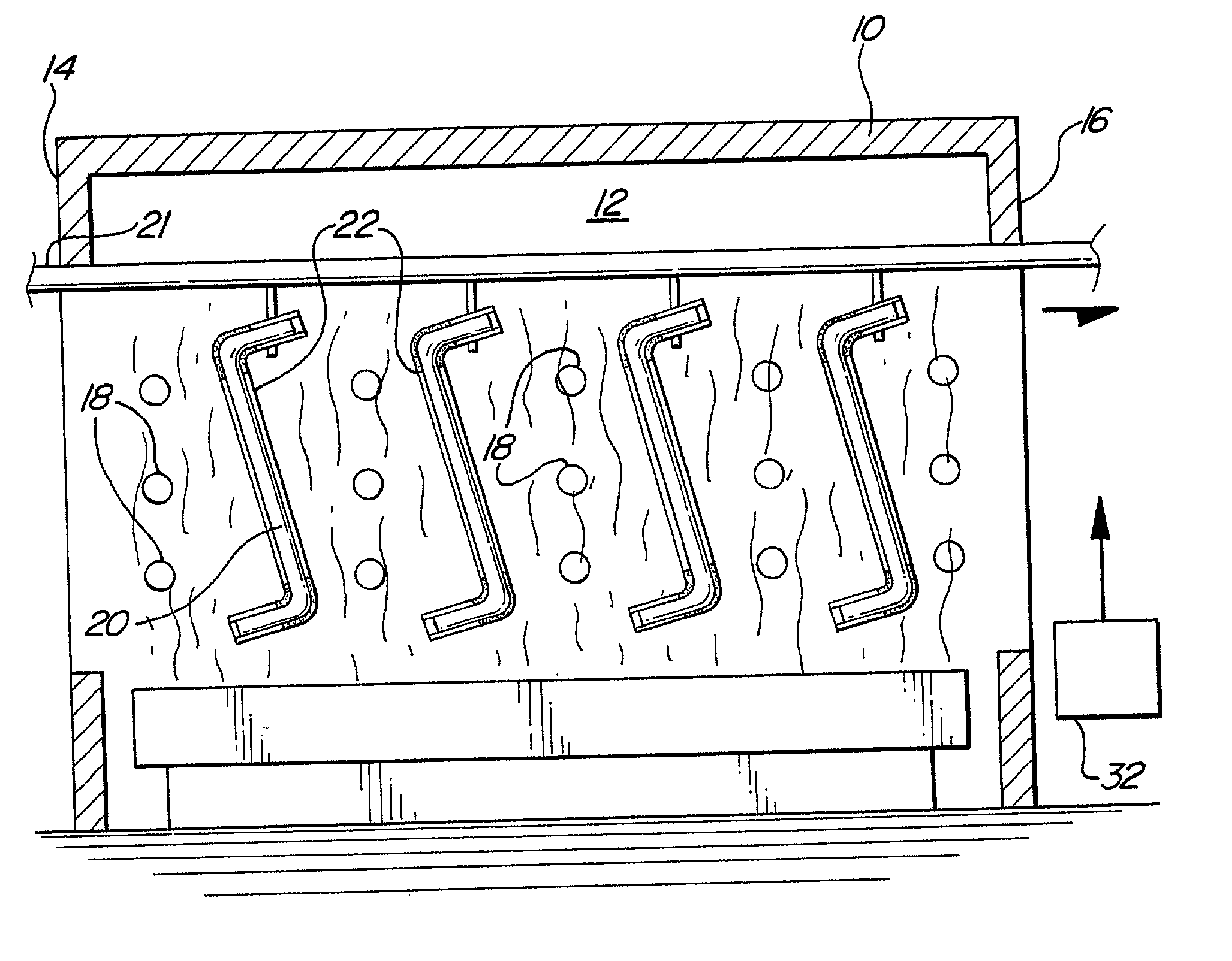
[0022] With reference first to FIG. 2, a preferred embodiment of the present invention is there shown and comprises an oven 10 defining an interior oven chamber 12. The oven chamber 12, furthermore, includes an inlet end 14 and an outlet end 16.

[0023] Any conventional means is utilized to heat the interior chamber 12 of the oven 10. However, as shown in FIG. 2, one or more banks of radiant heaters 18 are provided around the outer periphery of the oven chamber 12. These radiant heaters 18, furthermore, are sufficient to heat the oven chamber 12 to a temperature approaching that at which a thermoplastic tube 20 thermally deforms.

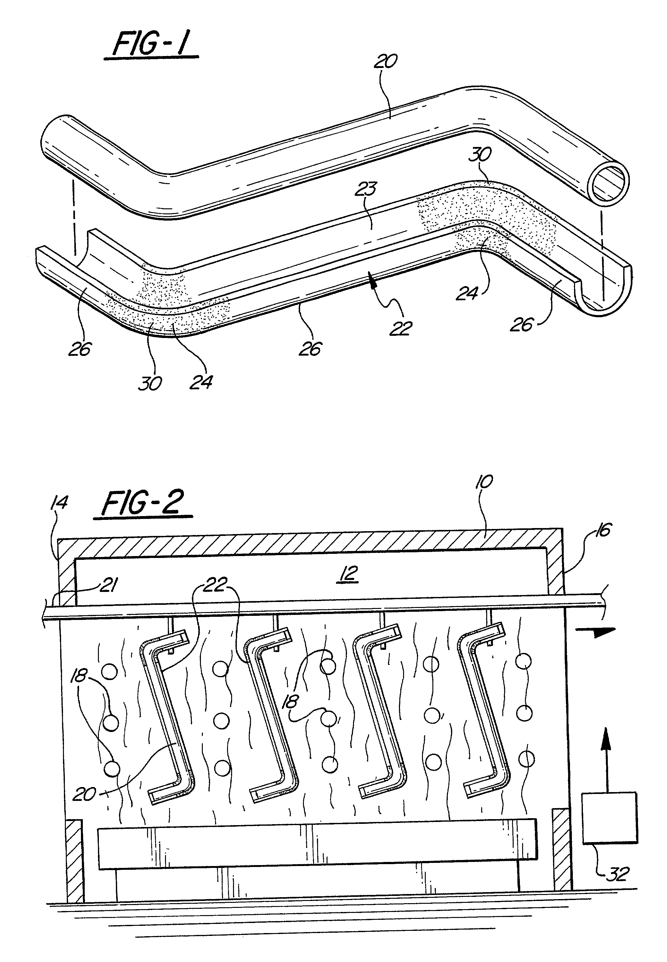
[0024] Still referring to FIG. 2, a conveyor 21, illustrated only diagrammatically, extends from the inlet end 14 and to the outlet end 16 of the oven chamber 12. One or more formers 22 are detachably secured to the conveyor 21 so that, upon actuation, the conveyor 21 conveys the formers 22 through the oven chamber 12.

[0025] With reference now to FIG. 1, one f...


PUM

PropertyMeasurementUnit
temperatureaaaaaaaaaa
flexibleaaaaaaaaaa
transparentaaaaaaaaaa

Abstract

An apparatus is disclosed for thermosetting thermoplastic tubes in a predefined shape having at least one bend. The apparatus includes an oven with an interior chamber which is heated to a temperature approaching that at which the tube thermally deforms. An elongated former has a channel dimensioned to receive the tube, and this channel has the predefined shape. A thermally absorbent coating is disposed only on a surface of the former adjacent to and extending across each bend of the former. This thermally absorbent coating locally adds the thermal energy required to reset the memory of the tube at the bend location. A conveyor extends through the oven chamber from an inlet end and to an outlet end of the oven, and the former is attached to the conveyor.

Description

[0001] I. Field of the Invention[0002] The present invention relates to an apparatus for thermosetting thermoplastic tubes in predefined shapes.[0003] II. Description of the Prior Art[0004] Tubes of a thermoplastic material are used in a wide variety of applications, e.g. the automotive industry. In the automotive industry, such thermoplastic tubes are used as fuel conduits for vapor, fuel, hydraulic, cooling and / or oil. In such applications, the tube is oftentimes required to be in a specific shape or configuration prior to its installation in the automotive vehicle.[0005] Previously, in order to form the thermoplastic tube into a specific shape, the thermoplastic tube was inserted into or onto a former which bent the tube into the desired shape. After the tube was inserted into the former and held in the desired shape, it was necessary to heat the thermoplastic material to a temperature at which the thermoplastic material thermally deforms. Following such deformation, the thermopl...

Claims


Application Information

Patent Timeline
Patent Type & Authority Applications(United States)
IPC IPC(8): B29C33/56B29C35/00B29C53/08B29C53/84
CPCB29C33/56B29C35/00B29K2101/12B29C53/84B29C53/083
Inventor RIGGS, RICHARD H.GABBEY, DAVID JOHNMARION, PATRICK L.
Owner MARTINREA IND INC
Why Eureka
Try Eureka