Hermetically sealed package

a hermetically sealed, packaging technology, applied in the direction of electrical apparatus casing/cabinet/drawer, electrical apparatus connection, semiconductor/solid-state device details, etc., can solve the problems of complex design of multi-layered ceramic structure, high manufacturing cost, and difficult to provide and sustain a good hermetically sealed seal along the edges and corners of ceramic inserts, and between ceramic inserts and the walls of the packag

Inactive Publication Date: 2003-04-10
CIT GRP BUSINESS CREDIT
View PDF0 Cites 22 Cited by
  • Summary
  • Abstract
  • Description
  • Claims
  • Application Information

AI Technical Summary

Benefits of technology

0011] In one embodiment of the invention, the portion of the conductive leads extending within the package also functions as a means to support the ceramic insert and secure it in position.

Problems solved by technology

There are several disadvantages to the package and structure shown in FIG. 1.
The multi-layered ceramic structure is very complicated in design and therefore expensive and difficult to manufacture.
The multi-layered rectangular ceramic inserts mounted in and secured to, and within, the side walls make it difficult to provide and sustain a good hermetic seal along the edges and corners of the ceramic insert, between the ceramic insert and the walls of the package.
However, brazing the rectangular multi-layered ceramic inserts into the sidewalls is subject to manufacturing yield loss.
However, the basic package with its ceramic insert and leads in place can not be used interchangeably with any other electronic circuit.

Method used


Image

  • Hermetically sealed package
  • Hermetically sealed package
  • Hermetically sealed package

Examples


Embodiment Construction

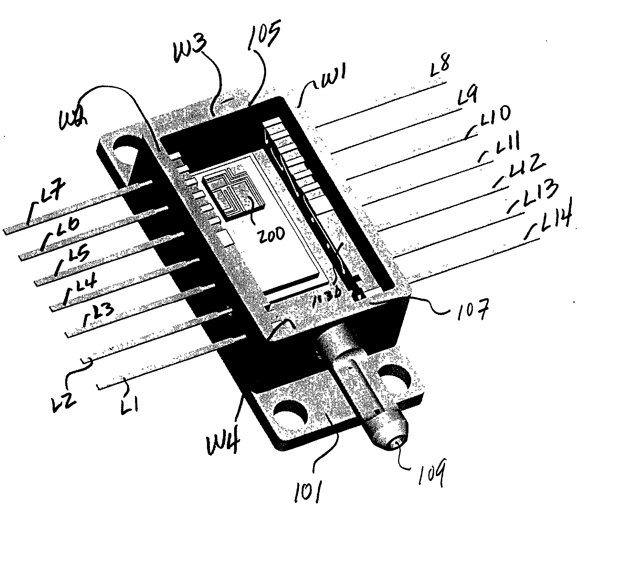
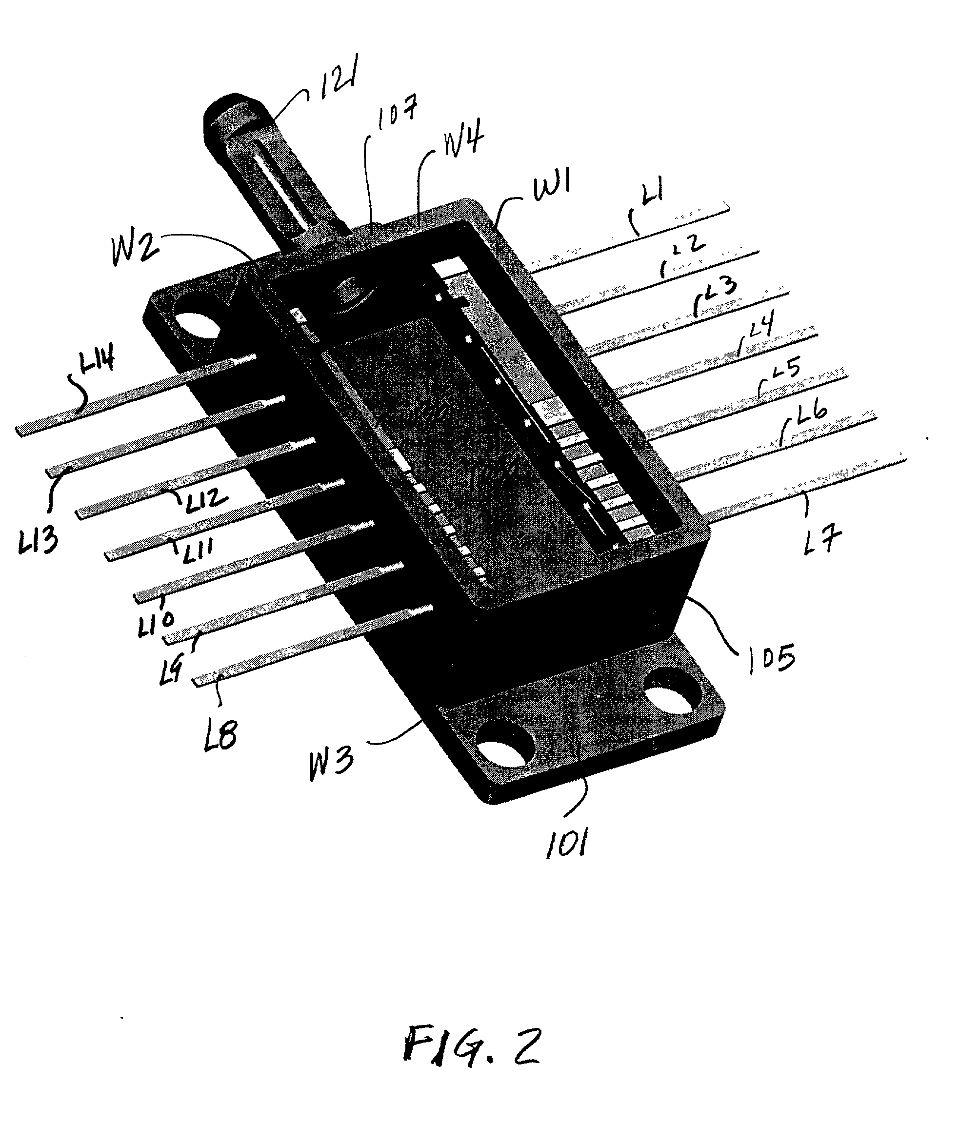
[0025] Applicants' invention may be explained beginning with reference to the package shown in FIG. 2. The package of FIG. 2 includes a base 101 which may be formed of copper or tungsten copper or any suitable material for providing good thermal conduction (heat sinking capability). The body of the package includes four side walls (W1, W2, W3, W4) which are mounted on the base 101. The walls may be formed of Kovar (iron nickel cobalt) or any other suitable material. Kovar is selected because its expansion coefficient matches that of glass. However, any other suitable material may be used.

[0026] In the package shown in FIG. 2, conductive leads (e.g., L1-L14) are mounted on two opposite side walls (e.g., W1, W2). The leads are mounted and secured to the side walls by means of glass performs (e.g., glass beads located in holes in the walls). The leads extend from outside each side wall to a short distance beyond the inside of each side wall. By way of example, in the package of FIG. 2 ...


PUM


Abstract

A package embodying the invention includes a base plate for receiving an electronic device having input/output points to be connected to an external system. Side walls mounted on the base plate enclose the electronic device. Selected side walls have a plurality of hermetically sealed openings through which are passed conductive leads which extend from within the package to outside the package for connecting the electronic device to the external system. A ceramic insert is mounted on the inside of at least one of the side walls. The ceramic insert has a first set of holes (terminals) for the direct contacting and connection thereto of selected conductive leads. The ceramic insert also has a second set of terminals whose layout is customized for optimally connecting selected ones of the second set of terminals to selected input/output points of the electronic device. The ceramic insert also includes a custom designed conductive pattern interconnecting selected ones of the first and second set of terminals.

Description

CROSS REFERENCE TO RELATED APPLICATIONS[0001] This application claims priority from provisional patent application Serial Number 60 / 327,978 filed Oct. 09, 2001 for Hermetically Sealed Package in the name of Robert J. Satriano and Caesar Morte.BACKGROUND OF THE INVENTION[0002] This invention relates to an improved hermetically sealed package.[0003] To better understand the description of the invention to follow, reference is made to FIG. 1 which shows a presently available hermetically sealed dual-in-line (DIL) package. The package of FIG. 1 includes a base, B1, with side walls (W1, W2, W3, and W4) mounted on the base. The base B1 may be formed of copper or tungsten copper, or any other suitable material, to provide good heat conduction. Mounted in, and secured to, each one of two opposing side walls is a multi-layered ceramic insert (C1, C2) which extends from the outside of each sidewall to the inside of each sidewall. In FIG. 1, a portion C2A of insert C2 is shown extending outsid...

Claims


Application Information

Patent Timeline
Patent Type & Authority Applications(United States)
IPC IPC(8): G02B6/42H01L23/047H01R13/52H05K5/00
CPCG02B6/4201G02B6/4248H01L23/047H01R13/5208H01L2224/48091H05K5/0095H01L2924/00014G02B6/4251G02B6/4256
Inventor MORTE, CAESARSATRIANO, ROBERT J.
Owner CIT GRP BUSINESS CREDIT
Why Eureka
Try Eureka