
Exercise machine

a technology of exercise machine and muscle, which is applied in the field of exercise machine, can solve the problems of inordinate complexity of commercially available devices of this type for enhancing muscle development, occupying a substantial amount of floor space, and conventional exercise machines are often rather complex in their construction

Inactive Publication Date: 2003-04-10
MULTI GRIP
View PDF10 Cites 18 Cited by
  • Summary
  • Abstract
  • Description
  • Claims
  • Application Information

AI Technical Summary

Benefits of technology

[0010] The muscle development machine of the invention is also extremely simple, yet effective in construction. The simplicity of its construction allows it to be assembled without difficulty by most users. Also, the simplicity of construction makes the exercise machine of the invention relatively inexpensive to fabricate. This reduces the cost of manufacture, thereby reducing the cost to the ultimate user.
[0011] The simplicity of construction also provides the exercise machine of the invention with smooth, aesthetically pleasing lines. This is important to many individuals since the device, once assembled, is typically within sight of the user and others in the user's dwelling a great deal of the time.
[0012] One of the biggest advantages of the exercise machine of the invention is its versatility. The muscle development machine of the invention employs a plurality of pulleys which may be positioned longitudinally along the length of an upright column in an infinitely adjustable manner. The feature of infinite adjustment of the position of many of the pulleys allows each individual user to utilize the machine in the most comfortable and effective manner possible, irrespective of the height, weight, physical stature, or stance of the user. The locations of the adjustable pulleys along the length of the column are quickly and easily adapted to the personal preferences of each user.
[0013] The ability to adjust the position of some of the pulleys is also advantageous in that the length of the cable extending from the pulley closest to the user may be adjusted to the maximum comfort of the user. By raising or lowering one of a plurality of the pulleys along the length of the column, the user can not only adjust the angle at which the cable extends from the final pulley toward the user, but also the length of that portion of the cable emanating from the final pulley.
[0015] The column is preferably formed as an elongated, extruded metal tubular structure having different channeled sides in which the plurality of tracks are formed. The column preferably has a generally rectangular cross-sectional configuration and the tracks are preferably formed as T-shaped channels in some or all of the sides of the column. This construction provides the column with overhanging flanges along the sides of the channels to laterally confine movement of structural elements of the machine that are longitudinally movable or positionable along the tracks.

Problems solved by technology

Many of the commercially available devices of this type for enhancing muscle development are inordinately complex and occupy a substantial amount of floor space when assembled.
Also, conventional exercise machines are frequently rather complex in their construction.
They often require expertise in their assembly that is beyond the ability of many users.
Moreover, complexity in construction typically significantly increases the cost of an exercise machine.
Another problem with conventional exercise machines is that they lack versatility in performing different exercises and in allowing users of different statures and physiques to engage in muscle development in the manner that is most effective for each individual user.
Due to height differences, weight differences, differences in stances, and differences in personal preferences, the location of the handgrip or other limb-engaging device on an exercise machine for one user is often uncomfortable, and sometimes even painful, when employed by another user.

Method used


Image

  • Exercise machine
  • Exercise machine
  • Exercise machine

Examples


Embodiment Construction

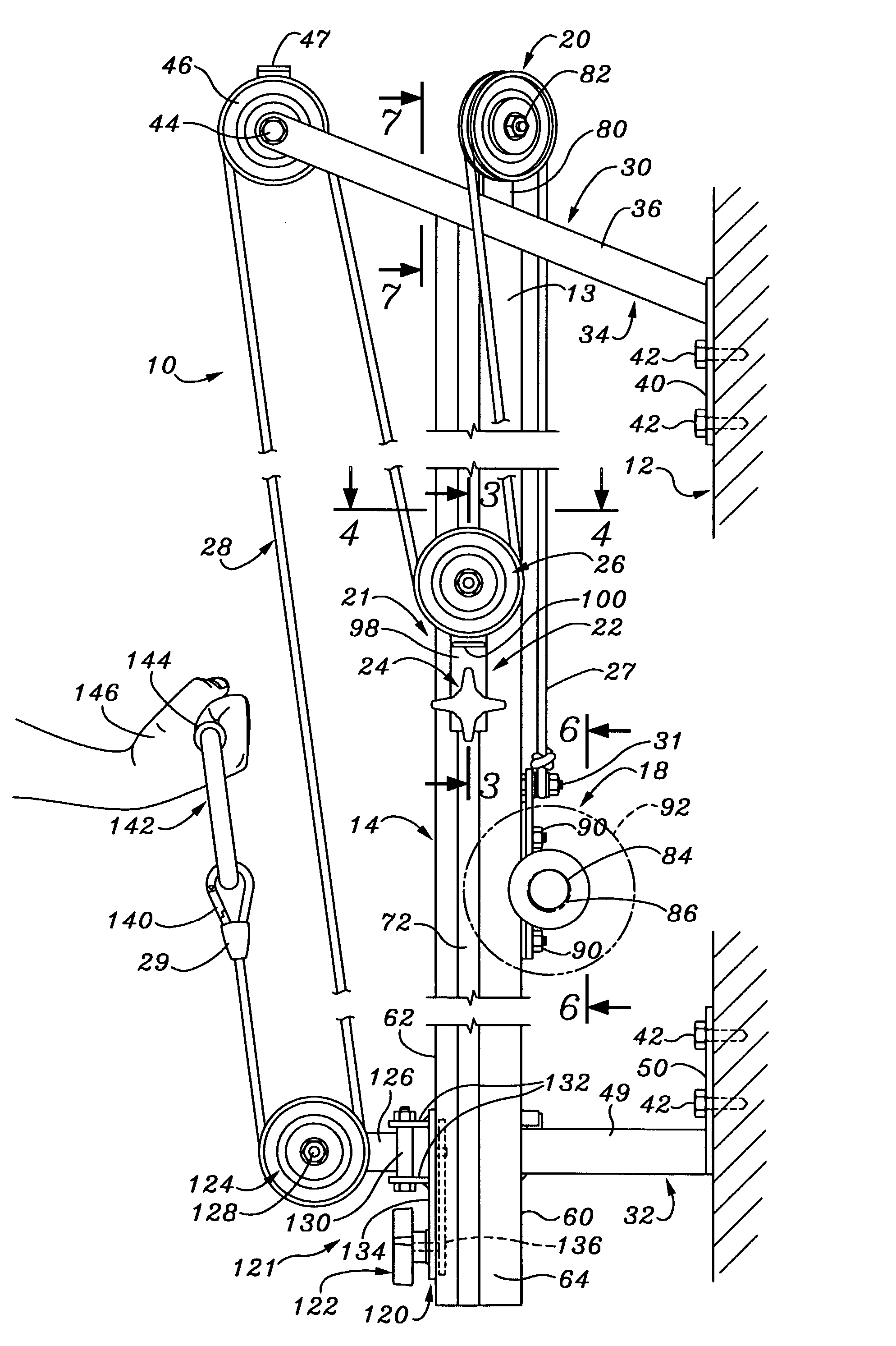
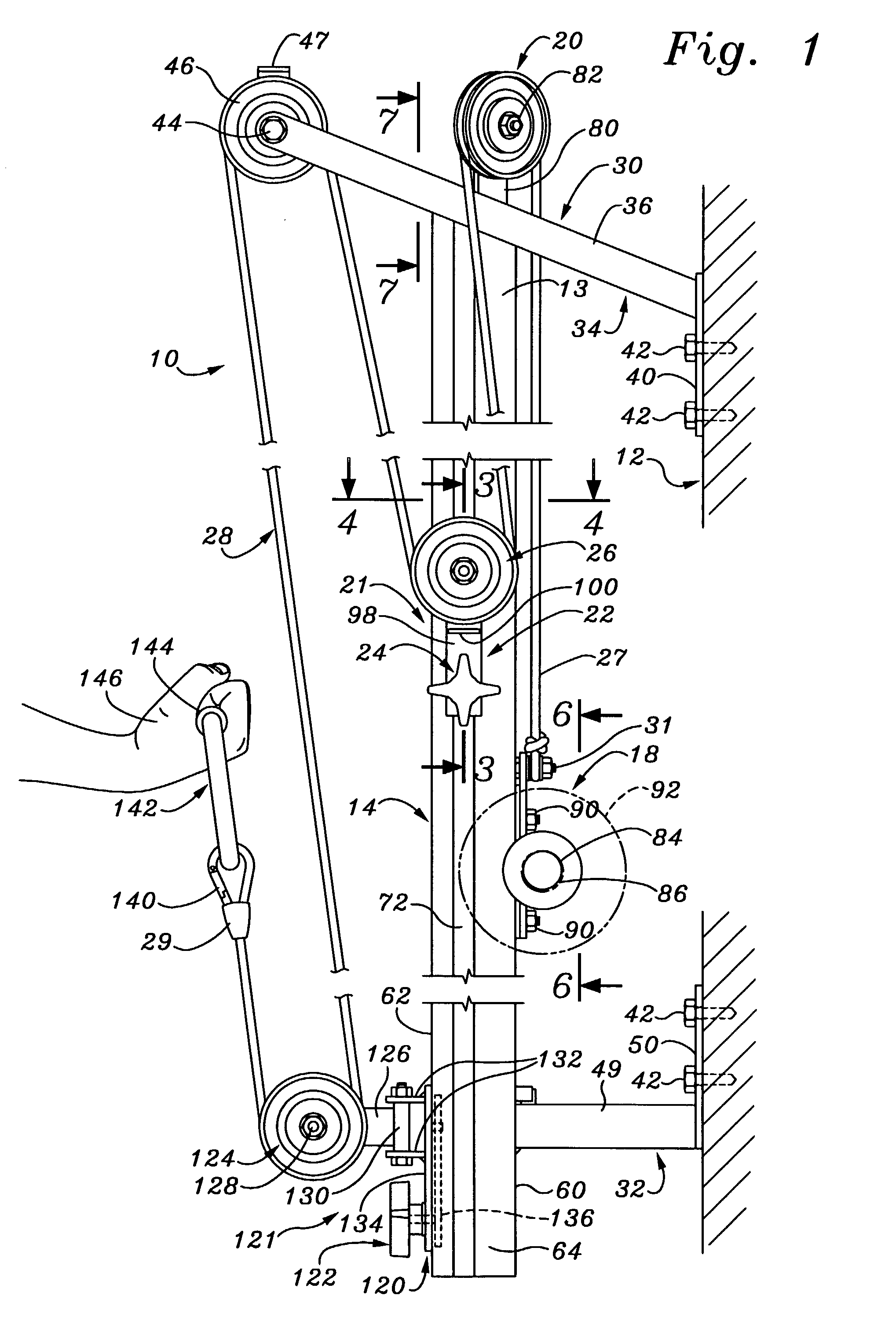
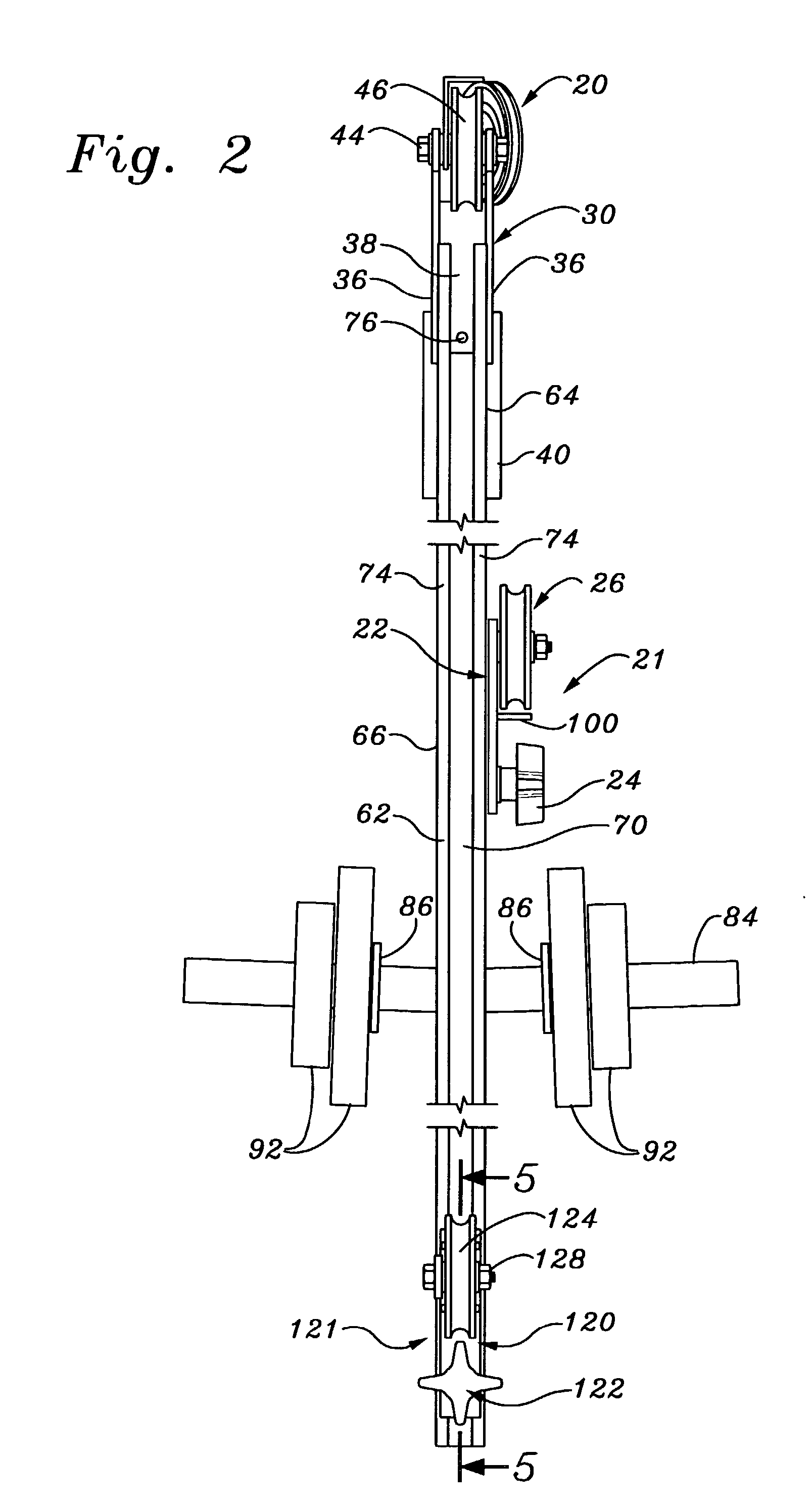
[0039] FIG. 1 illustrates an exercise machine or muscle development machine indicated generally at 10 assembled and installed for use near a vertical surface 12, such as the wall of a dwelling or garage, or attached to a stand. The physical development or exercise machine 10 is comprised of a longitudinally elongated, channeled column 14 supported in a vertical orientation, a weight carriage 18, an upper pulley 20, a first turning pulley assembly 21 a second turning pulley assembly 121, a cantilevered pulley 46, and a single cable 28 formed of polyester rope.

[0040] The longitudinally elongated column 14 has upper and lower ends 13 and 15, respectively. The column 14 is about seven feet in length and is supported in a vertical orientation by an upper mounting bracket 30 and a lower mounting bracket 32. The upper and lower mounting brackets 30 and 32 are made from a combination of rectangular steel tubing and flat steel welded together. The upper bracket 30 is formed with a top mounti...


PUM


Abstract

A physical development exercise machine is comprised of a longitudinally elongated, extruded metal column rigidly preferably attached to a vertical support, such as a wall, in spaced separation therefrom. The column includes a plurality of longitudinal, parallel tracks. A weight carriage is engaged for reciprocal movement in the vertical track located on the side of the column opposite the user. At least a first turning pulley slide, and preferably a second turning pulley slide are engaged in other of the vertical tracks. An upper pulley is mounted at the upper end of the column. Turning pulley slide locks are provided to releaseably immobilize the slides upon which the turning pulleys are mounted relative to the elongated column. A single weight-lifting cable is employed and is attached to the weight carriage and looped through the upper pulley and one or more of the turning pulleys.

Description

[0001] This application claims the priority of provisional application serial No. 60 / 327,745, filed Oct. 9, 2001.[0002] 1. Field of the Invention[0003] The present invention relates to a machine useful for muscle development by individuals, both for physical conditioning and for physical rehabilitation.[0004] 2. Description of the Prior Art[0005] Various exercise machines have been devised for use in enabling individuals to develop their muscles. It is well known that exercise of a muscle enhances its development. Therefore, numerous devices exist that provide hand grips or limb-engaging attachments by means of which an individual overcomes a force in order to apply stress to a muscle. Repeated muscular stress performed in a regimen of periodic exercises results in an increase in muscle development and strength.[0006] Many of the commercially available devices of this type for enhancing muscle development are inordinately complex and occupy a substantial amount of floor space when a...

Claims


Application Information

Patent Timeline
Patent Type & Authority Applications(United States)
IPC IPC(8): A63B21/00A63B21/062
CPCA63B21/062A63B21/154A63B2225/09A63B2021/0614A63B2021/169A63B21/156A63B21/0626A63B21/0628A63B21/169
Inventor WILLIAMS, PATRICK
Owner MULTI GRIP
Learn More