Method for producing a magnetically excitable core comprising a core winding for an electric machine

a technology of magnetic excitability and electric machines, which is applied in the direction of magnetic bodies, manufacturing stator/rotor bodies, magnetic circuit shapes/forms/constructions, etc., and can solve problems such as unoptimized fill factor

Inactive Publication Date: 2003-04-17
SEG AUTOMOTIVE GERMANY GMBH
View PDF11 Cites 41 Cited by
  • Summary
  • Abstract
  • Description
  • Claims
  • Application Information

AI Technical Summary

Problems solved by technology

In this prior art, it is disadvantageous that despite the good access to the slots, the fill factor is not optimal.

Method used


Image

  • Method for producing a magnetically excitable core comprising a core winding for an electric machine
  • Method for producing a magnetically excitable core comprising a core winding for an electric machine
  • Method for producing a magnetically excitable core comprising a core winding for an electric machine

Examples


Embodiment Construction

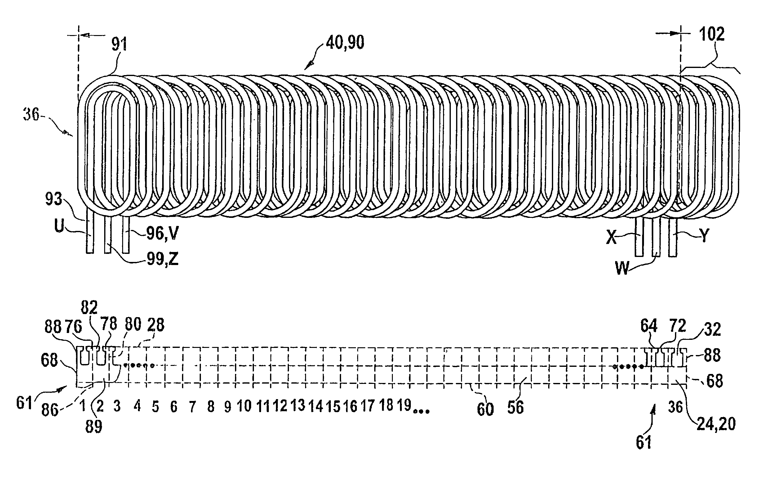
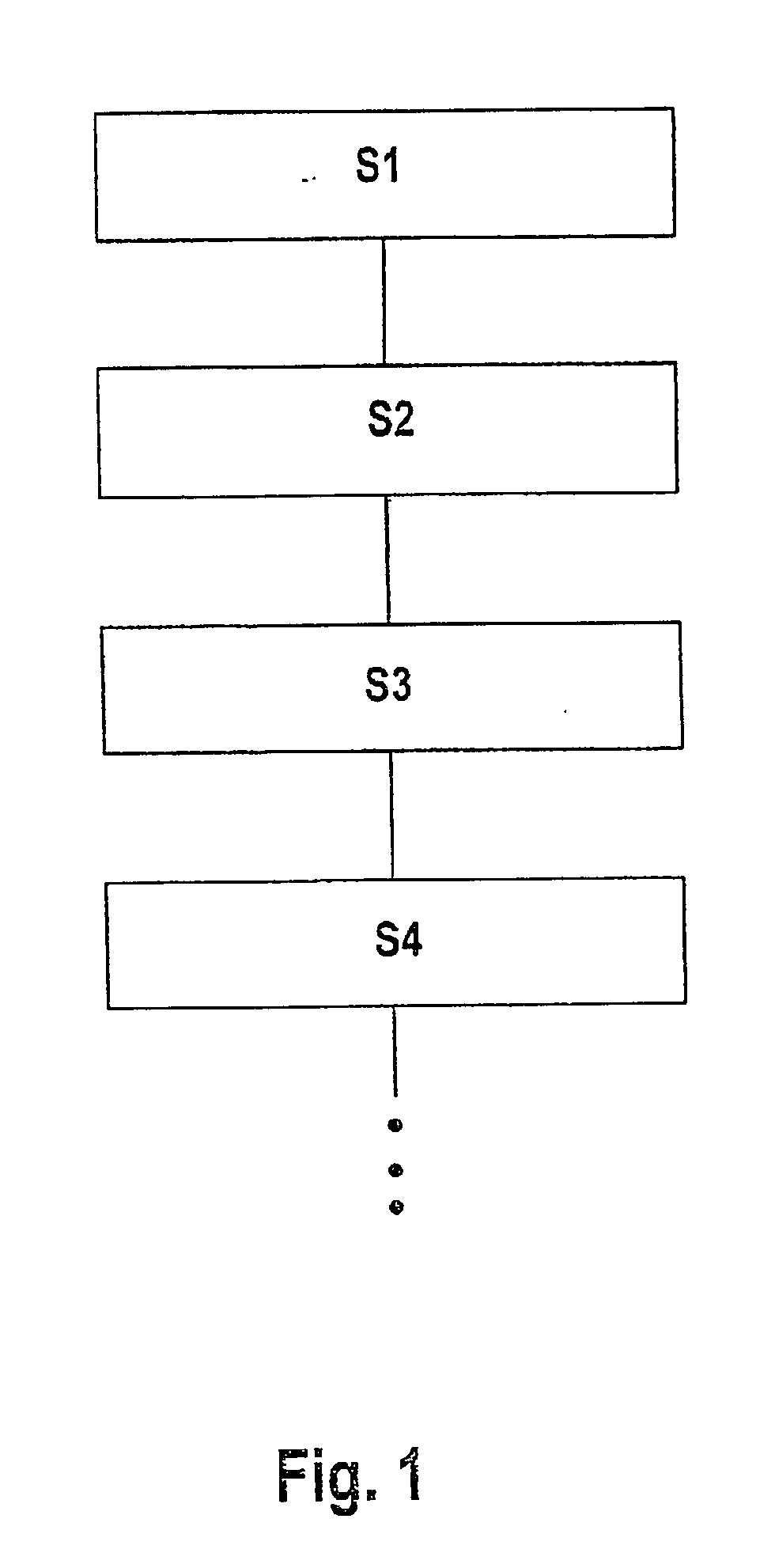
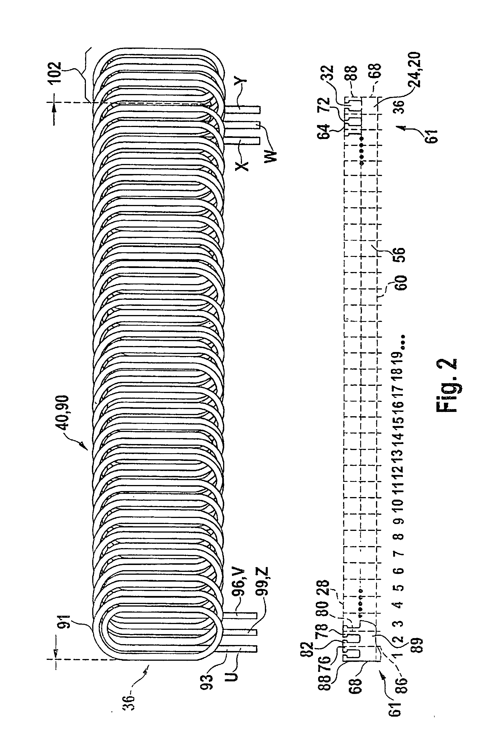
[0041] FIG. 1 is a schematic flow chart of the method of the invention, with the essential steps. In a method step S1, a magnetically excitable core 24 that has an essentially parallelepipiped shape 20 is made ready; see also FIG. 2. On one side 28, the core 24 has slots 32 extending parallel.

[0042] A core winding 40 has slot wire segments 105, which are later disposed in the slots 32. The slot wire segments 105, combined into a group and to be disposed in the slots 32, are called winding sides 36. The core winding 40 that has the winding sides 36 is pressed in a pressing tool 44 (FIG. 6B) in such a way that the winding sides 36 are reshaped and as a result adapted to the contour of a slot 32; this is method step S2. In a further, next method step S3, the pressed core winding 40 is inserted with its winding sides 36 into the slots 32 of the core 24; see also FIG. 8. In method step S4, the core 24 together with the core winding 40 is reshaped into a cylindrical ring shape 52, with ra...


PUM

PropertyMeasurementUnit
thicknessaaaaaaaaaa
shapeaaaaaaaaaa
axial widthaaaaaaaaaa

Abstract

A method for producing a magnetically excitable core (24) for an electrical machine, by which in a method step (S1), the core (24), having a substantially parallelepiped shape (20) with slots (32) extending parallel on one side, is furnished, into whose slots (32), in a method step (S2), the core winding (40) is inserted by its winding sides (36), and then in a method step (S3), the core (24) together with the core winding (40) is reshaped into a cylindrical ring shape (52) with radially inward-oriented slots (32), is proposed. The method is characterized by a further step, according to which in each case all winding sides (36) that are inserted into each slot (32) are pressed into a slot shape (119) in a tool (44) and reshaped before being inserted into the slot (32). Furthermore, a stator (150) produced by this method and an electrical machine (140) having this stator (150) are proposed.

Description

PRIOR ART[0001] From Japanese Published, Nonexamined Patent Application 9-103052, a production method for the stator of an electrical machine as generically defined by the preamble to claim 1 is already known.[0002] For producing this stator, first individual laminations are stamped out, and a certain number of these laminations are stacked, covering one another, until the desired axial width of the core is reached. These stacked laminations form the stator core, which thus on one side has typical teeth and slots, oriented parallel to one another, for a stator. An already prewound core winding, embodied as a distributed wave winding, is in approximately flat form and is then inserted into the slots of the substantially flat core. The flat component unit comprising the core and the core winding has a so-called winding overhang; that is, each individual one of a total of three phases has a winding side which initially is not inserted into slots. This component unit comprising the core...

Claims


Application Information

Patent Timeline
Patent Type & Authority Applications(United States)
IPC IPC(8): H02K1/16H02K1/18H02K15/02H02K15/06
CPCH02K15/024H02K15/066Y10T29/49071Y10T29/49078Y10T29/49009Y10T29/49073H02K1/12H02K15/02
Inventor KREUZER, HELMUTRAU, EBERHARDWILLMOTT, ADAMFUSSEY, ALANNEIL, WILLIAMSHENNE, MARTIN
Owner SEG AUTOMOTIVE GERMANY GMBH
Why Eureka
Try Eureka