Optical inspection method and apparatus having an enhanced height sensitivity region and roughness filtering

a height sensitivity region and optical inspection technology, applied in the field of optical inspection systems, can solve problems such as reducing the reliability of integrated circuits, destroying storage systems, and affecting the operation of inspection equipment,

Inactive Publication Date: 2003-04-24
XYRATEX CORP
View PDF0 Cites 18 Cited by
  • Summary
  • Abstract
  • Description
  • Claims
  • Application Information

AI Technical Summary

Problems solved by technology

If a defect sufficiently high collides with the storage system head assembly, the storage system may be destroyed or damaged.
Defects of significant height may cause shorting between layers within an integrated circuit and may also reduce reliability of integrated circuits that appear otherwise functional after manufacture.
Near field inspection systems may be used to resolve small defects, but since the near-field is confined to a relatively small height above the surface under inspection, it must scan the surface very slowly to avoid collision with the surface and if defects of significant height exist, the near-field probe may be damaged by collision with a defect.
However, standard far-field inspection systems are unsuitable for detecting small profile defects having significant height to above the average surface.
Any optical inspection system has resolution limits.
Small sub-wavelength defects and surface variations approach point source behavior, which will cause reflected energy to be dispersed throughout a half-plane (180 degree solid angle) above a surface under inspection.
Therefore existing far-field optical systems cannot discriminate between small defects and normal roughness variations.
Thus, existing far-field optical inspection systems are unsuitable for inspecting surfaces for small defects.
Since the profile of a defect that may cause damage to a media storage device or shorting in an integrated circuit wafer may be very small, existing far-field inspection systems are unsuitable for detecting the above-mentioned defects.

Method used


Image

  • Optical inspection method and apparatus having an enhanced height sensitivity region and roughness filtering
  • Optical inspection method and apparatus having an enhanced height sensitivity region and roughness filtering
  • Optical inspection method and apparatus having an enhanced height sensitivity region and roughness filtering

Examples


Embodiment Construction

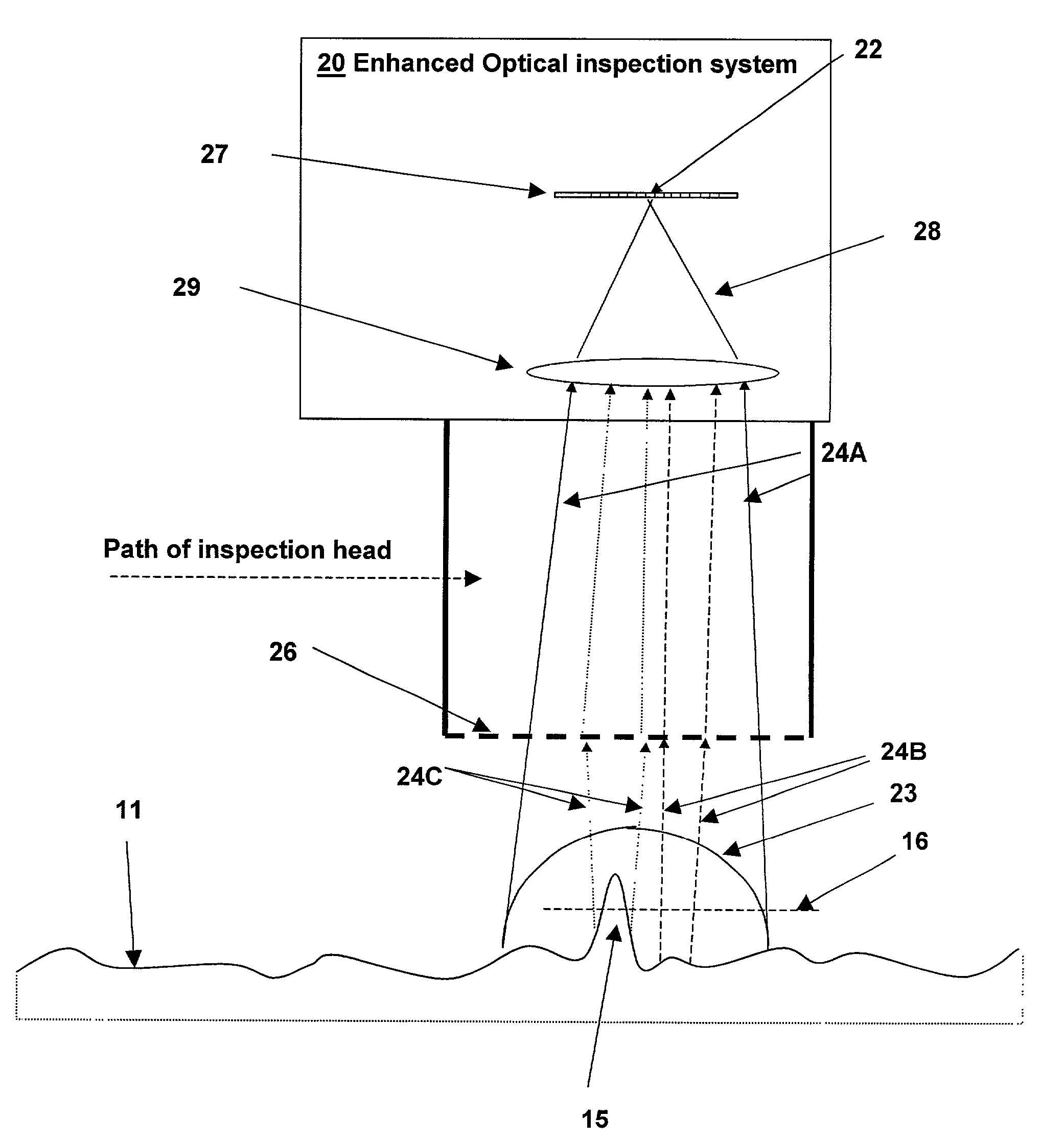
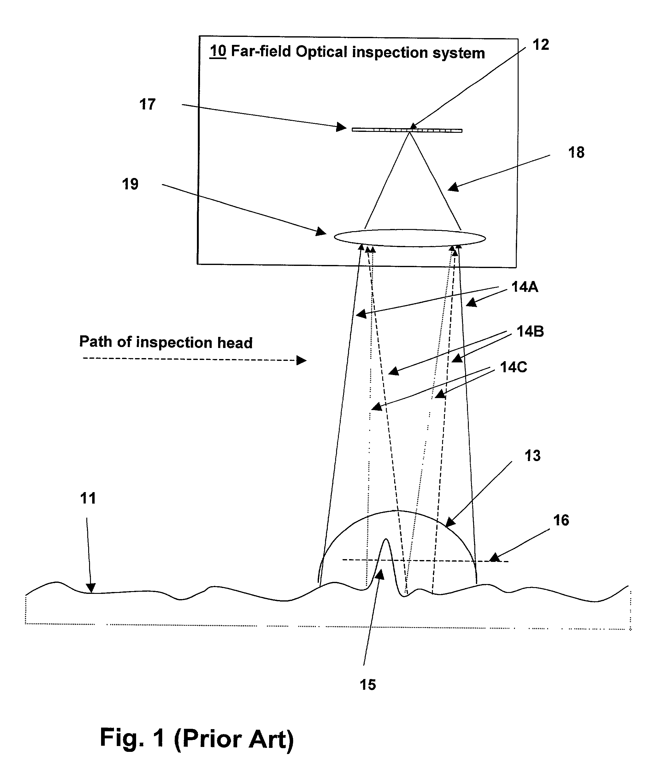
[0024] With reference now to the figures, and particularly to FIG. 1, a surface 11 under inspection by a prior art far-field optical inspection system 10 is depicted. Optical inspection system 10 is commonly known as an interferometric contrast microscope. Optical inspection system 10 includes a detector 12 shown here as a charge-coupled device (CCD) linear array, but other suitable detectors may be used. A lens 19 images light is reflected from a resolution cell 13 on surface 11 to a cell of CCD 12. The illumination path is not depicted in the illustration, nor is a reference path, as it is the reflected light that is pertinent to the description of the differences between the prior art and the present invention. Several resolution cells may thereby be scanned by detector 12 without moving the inspection head. Resolution cell 13 represents the optical resolution of imaging lens 19.

[0025] An illumination beam (not shown) is reflected by surface 11 to produce a reflected beam 14A. Th...


PUM

PropertyMeasurementUnit
heightaaaaaaaaaa
roughnessaaaaaaaaaa
roughnessaaaaaaaaaa

Abstract

An optical inspection method and apparatus having an enhanced height sensitivity region and roughness filtering uses a Fabry-Perot cavity to increase the phase detection sensitivity for light reflected from surface defects having a height above a predetermined level. A partially reflective surface is inserted between an illumination subsystem and a surface under inspection. The position of the partially reflective surface with respect to the surface under inspection is adjusted to provide both filtering of defects below the predetermined level and enhance sensitivity for a region of defect heights above the predetermined level. The angular resolution of the inspection system is improved, providing far-field inspection that can detect small-profile defects having unacceptable heights. Media storage, semiconductor wafer and other precision surface manufacture may be improved by use of the techniques of the present invention.

Description

[0001] This application is related to pending U.S. patent application Ser. No. 09 / 789,913 entitled "SYSTEM OF BEAM NARROWING FOR RESOLUTION ENHANCEMENT AND METHOD THEREFOR" filed on Feb. 21, 2001, the specification of which is incorporated in herein by reference.[0002] 1. Field of the Invention[0003] This invention relates to optical inspection systems, and more specifically, to an optical system incorporating a resonator to produce an enhanced sensitivity to defects with significant height and a filtering of surface roughness.[0004] 2. Description of the Related Art[0005] Precision surfaces are required in components used in many applications today. Storage media for use in both for optical and magnetic storage systems require surfaces that are free of defects having significant height above the mean surface of the media. If a defect sufficiently high collides with the storage system head assembly, the storage system may be destroyed or damaged.[0006] In semiconductor manufacturing...

Claims


Application Information

Patent Timeline
Patent Type & Authority Applications(United States)
IPC IPC(8): G01N21/57G01N21/88
CPCG01N21/8806G01N21/57
Inventor CLARK, BRYAN KEVIN
Owner XYRATEX CORP
Why Eureka
Try Eureka