

Solid-liquid filtering method and system for sewage, waste water and the like
- Summary
- Abstract
- Description
- Claims
- Application Information
AI Technical Summary
Benefits of technology
Problems solved by technology
Method used
Image

Examples
embodiments
[0029] Referring now to the drawings, the present invention will be further described by the following embodiments.
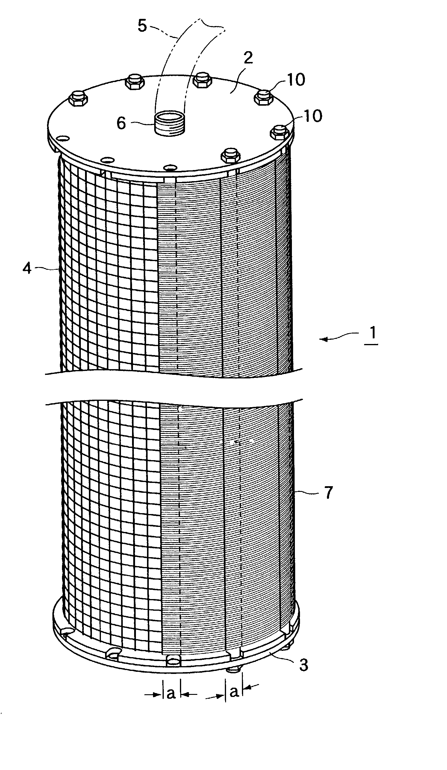
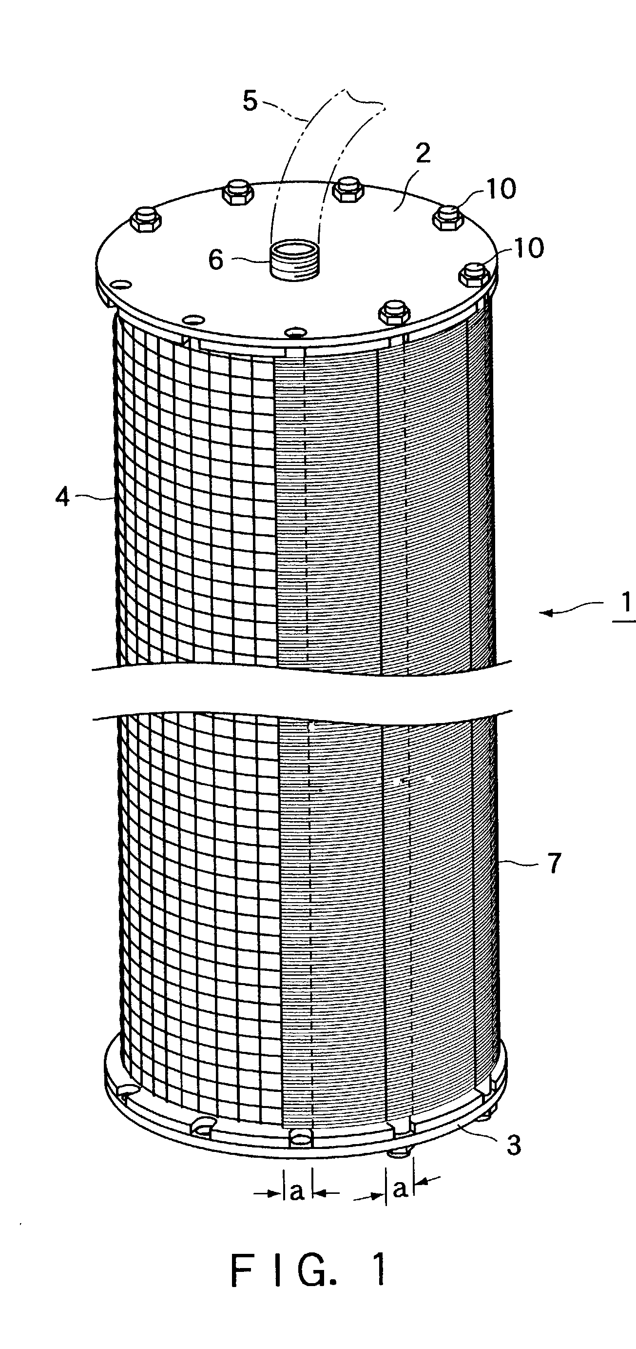
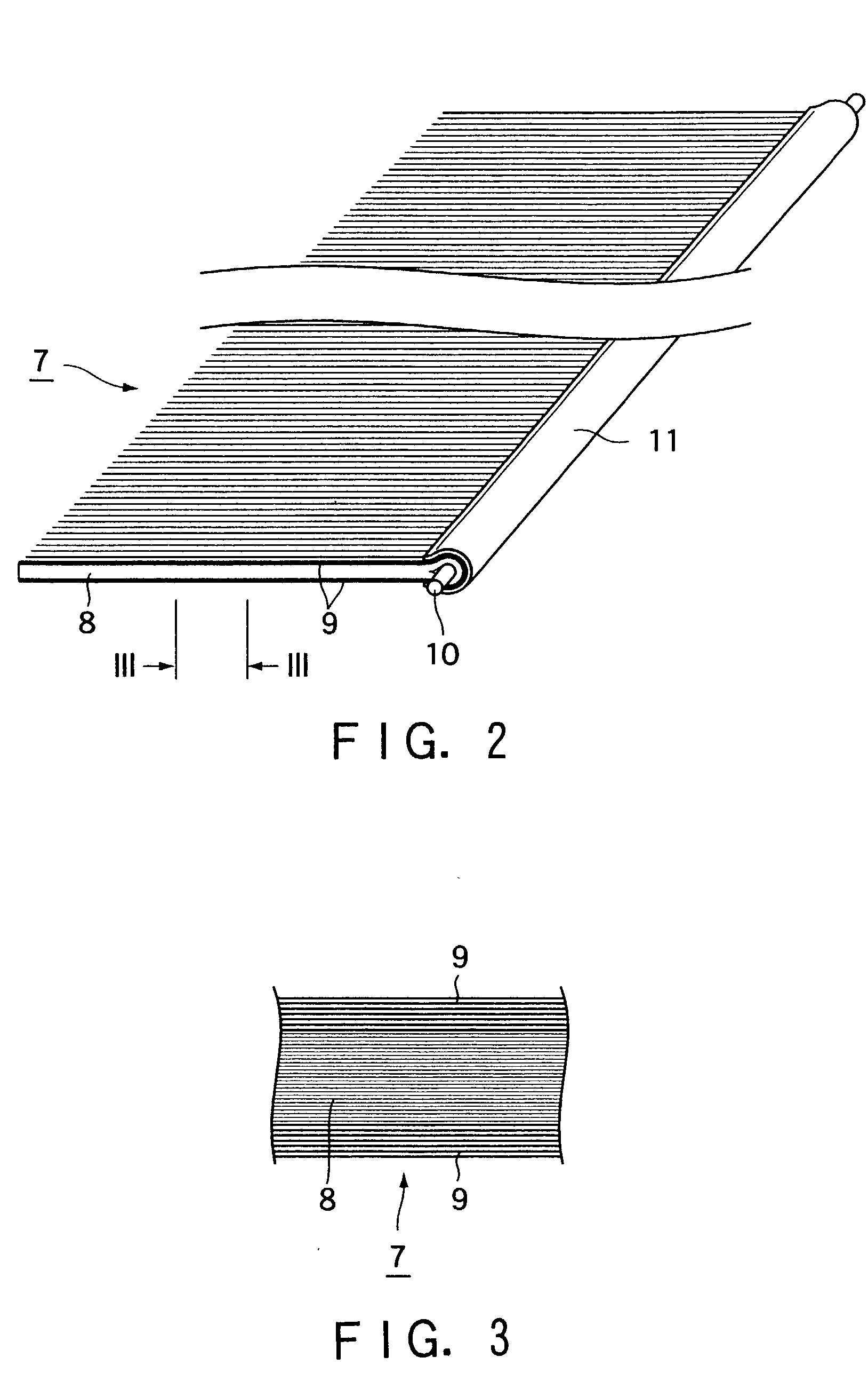
[0030] FIG. 1 is a perspective view of the present solid-liquid filtering system, FIG. 2 is a perspective view of a filter medium of the present solid-liquid filtering system, and FIG. 3 is a partially enlarged side view of a short side portion of the filter medium shown in FIG. 2 (taken on line III-III in FIG. 2). In FIG. 1, a series of bands of assembled monofilaments are partially taken off for better understanding.
[0031] 1 designates a cylindrical basket-like frame made of stainless steel as a part of the present system. The frame 1 is about 450 mm in length and about 140 mm in diameter. The frame 1 is provided with sealing lids 2 and 3 made of stainless steel on the top and bottom opening and a stainless wire screen 4 of about 1 cm mesh stretched thereon. The upper lid 2 is provided with a fitting 6 for detachably connecting an drawing pipe 5.
[0032] 7 designates a ...
PUM
| Property | Measurement | Unit |
|---|---|---|
| Diameter | aaaaa | aaaaa |
| Thickness | aaaaa | aaaaa |
| Length | aaaaa | aaaaa |
Abstract
Description
Claims
Application Information